DAF CF65, CF75, CF85 Series . Manual - part 517


  Index      DAF     DAF CF65, CF75, CF85 Series - service repair manual


Search            


Content   ..  515  516  517  518   ..


DAF CF65, CF75, CF85 Series . Manual - part 517


5

CF65/75/85 series ≥0E621376

General

READING DIAGRAMS

1-1

1. GENERAL

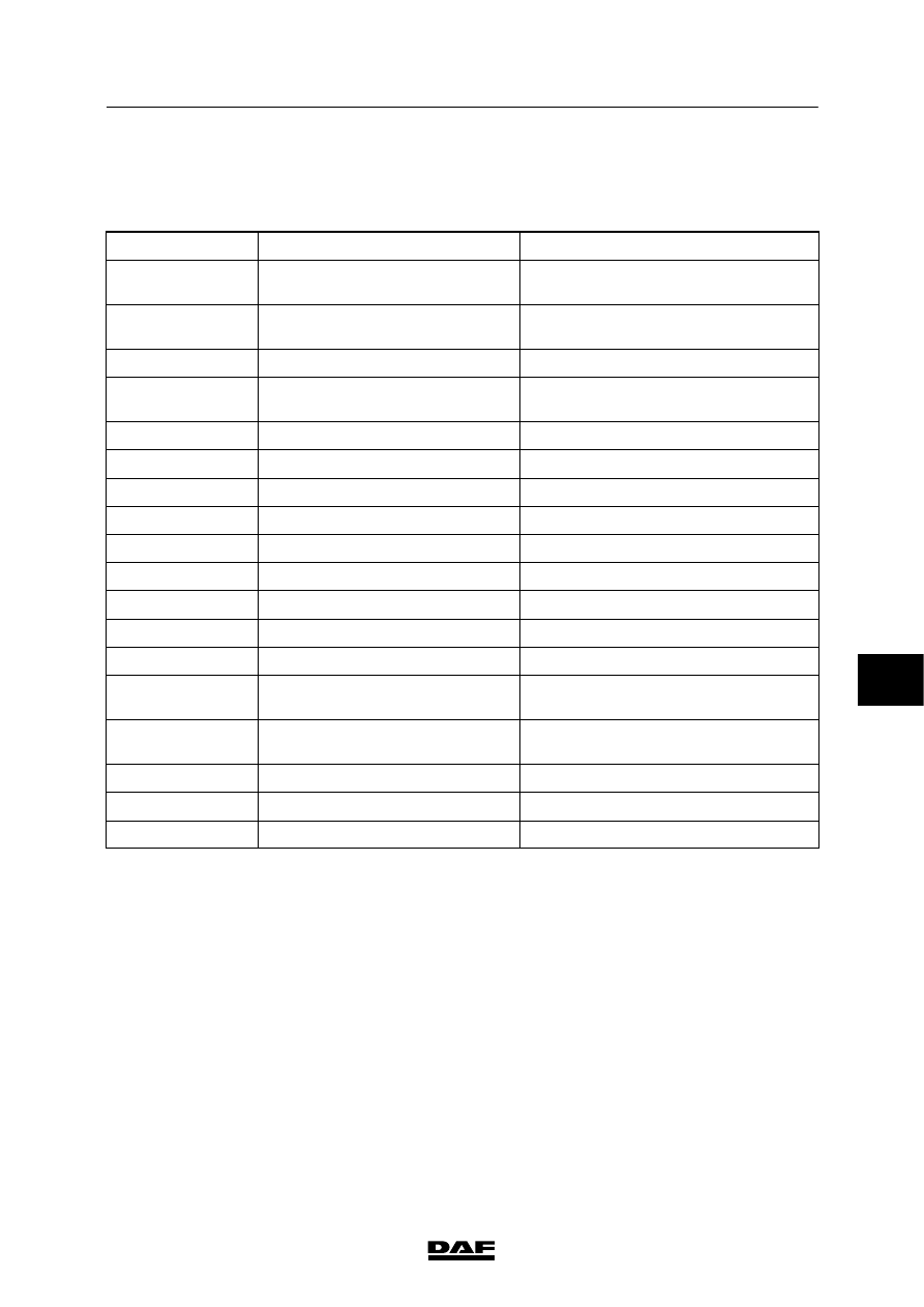
1.1 LIST OF ABBREVIATIONS

Abbreviation

Explanation

Translation/description

ABS/ASR-D

Anti Blocking System/Anti Slip

Control - version D

Antiblokkeersysteem/Antislipregeling,

versie D

ACH-E

Additional Cab Heater -

Eberspächer

Standverwarming - Eberspächer

ACH-W

Additional Cab Heater - Webasto

Standverwarming - Webasto

AGC-A

Automatic Gearbox Control -

Allison

Besturing automatische versnellingsbak

- Allison

AGS

Automatic Greasing System

Automatisch smeersysteem

AIRCO

Air conditioning

Airconditioning

ALS-S

Alarm system Scorpion

Alarmsysteem Scorpion

ASR

Anti Slip Control

Antislipregeling

CAN

Controller Area Network

Controller Area Network

CCU

CAN Connection Unit

CAN-verbindingsunit

CDB

Central Distribution Board

Centraalkast CF-serie

CDS

Central door locking

Centrale portiervergrendeling

CXB

CAN extension box

CAN-extensiebox

ECS-DC3

Engine Control System -

DAF/Cummins

Motormanagementsysteem

DAF/Cummins

DAVIE XD

DAF Vehicle Investigation

Equipment version XD

DAF-voertuigdiagnose-apparaat

versie XD

DEB

DAF Engine Brake

DAF-motorrem

DIP-4

DAF Instrument Pack

DAF-instrumentenpaneel

DVB

Connection

Doorverbinding

 200404

7

5

READING DIAGRAMS

General

CF65/75/85 series ≥0E621376

1-2

Abbreviation

Explanation

Translation/description

EBS

Electronic Brake System

Elektronisch remsysteem

ECAS-2

Electronically Controlled Air

Suspension - version 2

Elektronisch geregeld luchtveersysteem

- versie 2

ECAS3

Electronically Controlled Air

Suspension system - version 3

Elektronisch geregeld luchtveersysteem

- versie 3

ECS-DC3

Engine Control System -

DAF/Cummins

Motormanagementsysteem

DAF/Cummins

EMAS

Electronically controlled multi axle

steering

Elektronisch geregelde naloop assturing

EVS

Electronic Vehicle Steering system

Elektronisch voertuigstuursysteem

NMV

Engine specific power take off

Motor-PTO

NRM

Noise reduction module

Geluidsreducerende module

PTO

Power Take Off

Krachtafnemer

RAS-EC

Rear Axle Steering - Electronically

Controlled

Electronisch geregelde naloop assturing

Tacho MTCO

Modular Tachograph

Modulaire tachograaf

UPEC

Unit Pump Electronically

Controlled

Elektronisch gestuurde pompunit

VIC

Vehicle Intelligence Centre

Voertuig intelligente centrale

VLG/ ADR/

GGVS/ PETREG/

RTMDR

Overland transport of hazardous

substances

Vervoer gevaarlijke stoffen

7

 200404

5

CF65/75/85 series ≥0E621376

Marking of wiring

READING DIAGRAMS

2-1

2. MARKING OF ELECTRICAL WIRING

INTRODUCTION

This standard sets out specifications for the

uniform use of markings on electrical wiring.

The marking system consists of a numerical

system and a colour coding system, which

ensure a clear wiring layout and prevents faulty

connections and manufacturing errors.

The marking system does not apply to vehicles

subject to special conditions, such as military

vehicles.

Numerical and colour coding

Each numerical code consists of four digits, the

first of which refers to the main group and to the

colour.

Main groups

Power supply (red)
1000 to 1099

Voltage generation

1100 to 1199

Power supplies before

ignition

1200 to 1499

Power supplies after

ignition

Lighting (yellow)
2000 to 2099

Direction indicator lights

and alarm light

2100 to 2599

Vehicle external lights

2600 to 2999

Vehicle interior lighting

Warning and inspection functions (blue)
3000 to 3399

Engine functions

3400 to 3999

Vehicle functions

Consumers (black)
4000 to 4499

Starting, stopping, engine,

glow functions

4500 to 5499

Vehicle functions

5500 to 5999

Automatic transmission

Special applications (colour as desired)
6000 to 6999

Earth connections (white)
Not marked
9000 to 9499

Test and signal earth

7

 200404

5

READING DIAGRAMS

Marking of wiring

CF65/75/85 series ≥0E621376

2-2

I-CAN wiring (twisted)
3565

CAN-L (yellow)

3566

CAN-H (grey)

V-CAN wiring (twisted)
3700

CAN-L (yellow)

3701

CAN-H (blue)

Notes:

-

The “M” with serial number coding on earth

wiring is used for production-related

reasons.

-

In the case of straight splicing of the wiring

(cascading), the numerical codes are shown

on each separate wire followed by a serial

letter.

Earth connections

The application of electronic systems has made

it necessary to divide the earth connections into

groups. There is a distinction to be made

between two different types of earth connection:

-

switching earth

-

test and signal earth.

The switching earth is the conventional type of

earth.

The test and signal earth is used exclusively for

electronic systems.

The wiring colour for both types of earth is white,

but the test and signal earth wiring is marked

with numerical codes (from 9000 to 9500).

NEVER USE THE TEST AND SIGNAL

EARTH WHEN FITTING AN

ELECTRICAL COMPONENT

If you do this, electronic components may not

work correctly.

If an electronic component needs to be

connected, the earth for this system must be

connected to the central earth connection in the

cab.

The connection point is located in the dashboard

connector lead-through.

Abbreviations used in colour coding

Colour

Abbre-

viation

Colour

Abbre-

viation

red

rd

yellow

gl

brown

bn

white

wt

green

gn

grey

gs

blue

bw

black

zt

orange

oe

7

 200404


Content   ..  515  516  517  518   ..