DAF CF65, CF75, CF85 Series . Manual - part 487


  Index      DAF     DAF CF65, CF75, CF85 Series - service repair manual


Search            


Content   ..  485  486  487  488   ..


DAF CF65, CF75, CF85 Series . Manual - part 487


©

 200324

4-3

Removal and installation

XE ENGINE, ENGINE BRAKE

CF65/75/85 series

4

10

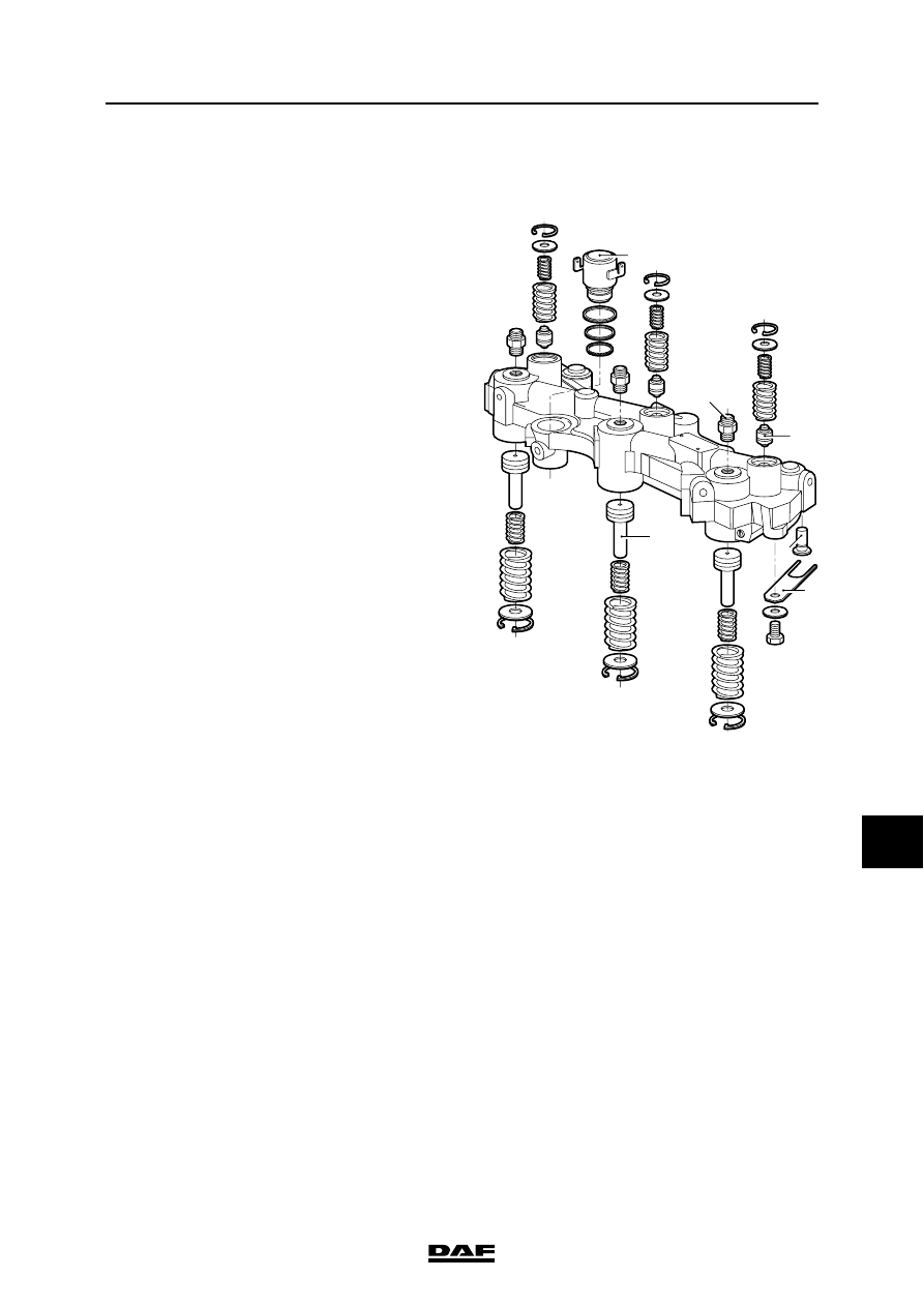
4.2 REMOVAL AND INSTALLATION, DEB SPRING PLATE

Removing the DEB spring plate
1.

Remove the DEB.

2.

Remove the spring plate (5) with shim and 

attachment bolt.

i400541

5

2

1

3

4

6

XE ENGINE, ENGINE BRAKE

4-4

©

 200324

Removal and installation

10

CF65/75/85 series

4

Installing the DEB spring plate

Note:

To prevent the spring plate being damaged and/

or broken, it should be positioned very carefully.

1.

Use the special tool (DAF no. 1329321) to 

position the spring plate (5) on the main 

piston (4).

2.

Fit the lock washer with fixing bolt and tighten 

it to the specified tightening torque. See 

"Technical data".

3.

Install the DEB and tighten the attachment 

bolts to the specified torque. See "Technical 

data".

i 400239

i400238

©

 200324

4-5

Removal and installation

XE ENGINE, ENGINE BRAKE

CF65/75/85 series

4

10

4.3 REMOVAL AND INSTALLATION OF EXHAUST BRAKE

Removing the exhaust brake
1.

Disconnect the air connection from the 

exhaust brake cylinder (8).

2.

Remove the heat shield (5).

3.

Remove the nuts attaching the exhaust 

brake (4) to the turbocharger (7).

4.

Remove the clamping strip from the exhaust 

pipe (3).

5.

Remove the entire exhaust brake (4).

Installation, exhaust brake
1.

Check the butterfly valve for smooth 

operation.

2.

Check the sealing faces of the exhaust brake 

(4) and the exhaust pipe (3).

3.

Clean the attachment bolts and apply heat-

resistant grease to the threads.

4.

Position the exhaust brake (4) between the 

turbocharger (7) and the exhaust pipe (3).

5.

Secure the clamping strip of the exhaust pipe 

(3), attach the turbocharger (7) on the 

exhaust manifold flange and secure the 

attachment nuts to the specified tightening 

torque. See "Technical data".

6.

Fasten the heat shield (5) and tighten the 

attachment bolts to the specified torque. See 

"Technical data".

7.

Check the setting of the exhaust brake; see 

"Inspection and adjustment".

i400671

6

7

3

1

2

5

4

8

XE ENGINE, ENGINE BRAKE

4-6

©

 200324

Removal and installation

10

CF65/75/85 series

4


Content   ..  485  486  487  488   ..