DAF CF65, CF75, CF85 Series . Manual - part 485


  Index      DAF     DAF CF65, CF75, CF85 Series - service repair manual


Search            


Content   ..  483  484  485  486   ..


DAF CF65, CF75, CF85 Series . Manual - part 485


©

 200324

2-15

General

XE ENGINE, ENGINE BRAKE

CF65/75/85 series

4

10

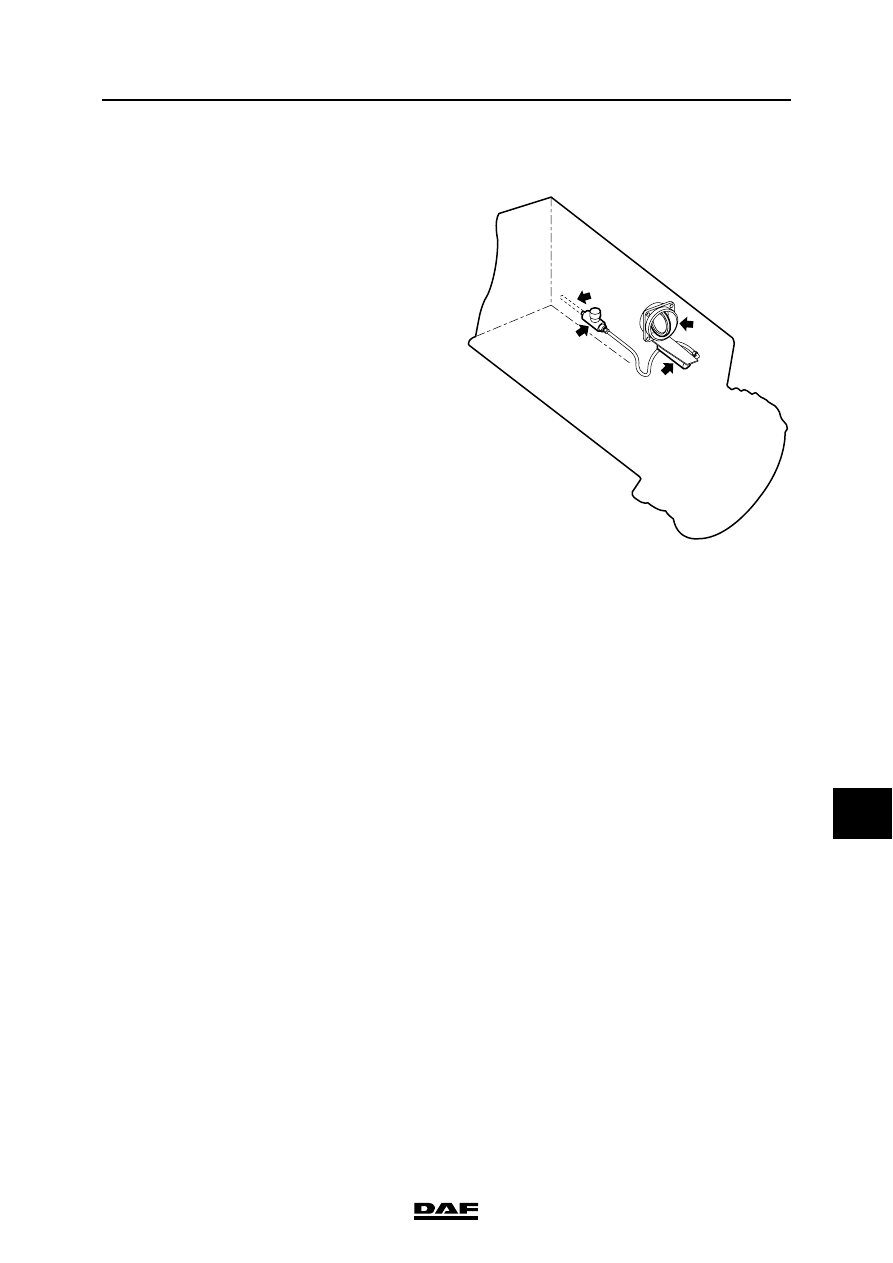
2.6 SYSTEM DESCRIPTION, EXHAUST BRAKE

Switching on the exhaust brake
The exhaust brake consists of an engine brake 

operating switch fitted in the cab floor and an 

operating cylinder (2) connected to the butterfly 

valve in the exhaust pipe.

If the engine brake control switch is operated, a 

signal is passed to the engine management 

system's electronic unit. The engine 

management system's electronic unit interrupts 

the fuel supply to the various cylinders. The unit 

also energises the exhaust brake valve, causing 

compressed air to flow to the operating cylinder 

(2). The cylinder closes the butterfly valve in the 

butterfly valve housing. The exhaust pipe is then 

almost completely closed off.

Controlled discharge of exhaust gases is still 

possible through a calibrated hole in the butterfly 

valve.

The engine now acts as a compressor, creating a 

braking action.

The higher the engine speed, the greater the 

braking action of the exhaust brake.

Switching off the exhaust brake
If the engine brake control switch is released, the 

fuel supply to the various cylinders will be re-

instated and the butterfly valve will be re-opened.

I400533

3

2

4

1

1.

Butterfly valve operating cylinder

2.

Exhaust brake valve

3.

Supply pressure

4.

Butterfly valve

XE ENGINE, ENGINE BRAKE

2-16

©

 200324

General

10

CF65/75/85 series

4

©

 200324

3-1

Inspection and adjustment

XE ENGINE, ENGINE BRAKE

CF65/75/85 series

4

10

3. INSPECTION AND ADJUSTMENT

3.1 INSPECTION AND ADJUSTMENT, DEB CLEARANCE

}

When the engine or parts thereof are 

opened, it is possible for dirt to 

penetrate which can result in serious 

damage to the engine. Therefore, the 

engine should be cleaned 

thoroughly before any parts are 

opened.

1.

Remove the valve covers.

2.

Tighten the DEB attachment bolts to the 

specified torque. See "Technical data".

3.

Using the special tool (DAF no. 1310477), 

crank the engine in the direction of rotation 

until cylinder 1 has reached the top dead 

centre (TDC) and the valves of cylinder 6 are 

in overlap position.

4.

Use set screw B to set the DEB clearance (A) 

of cylinders 1, 3 and 5. See "Technical data".

Tighten the lock nut to the specified torque. 

See "Technical data".

5.

Using the special tool (DAF no. 1310477), 

crank the engine in the direction of rotation 

until cylinder 6 has reached the top dead 

centre (TDC) and the valves of cylinder 1 are 

in overlap position.

6.

Use set screw B to set the DEB clearance (A) 

of cylinders 2, 4 and 6. See "Technical data".

7.

Tighten the lock nut to the specified torque. 

See "Technical data".

8.

Fit the valve covers.

B

A

i 400166

XE ENGINE, ENGINE BRAKE

3-2

©

 200324

Inspection and adjustment

10

CF65/75/85 series

4

3.2 FUNCTIONAL CHECK, DEB

Electrical inspection of DEB
1.

Disconnect both DEB connectors at the 

valve cover.

2.

Check the solenoid valve for an open circuit 

and for the correct resistance value using a 

multimeter (set to the resistance value 

position). See "Technical data".

3.

Check whether the solenoid valve is short-

circuited to the vehicle's earth.

4.

Connect a multimeter (set to the volt 

measuring position) to the engine cable 

harness.

5.

Start the engine and, using the accelerator 

pedal, increase the engine speed to approx. 

1500 rpm.

Activate the engine brake using the engine brake 

control switch on the cab floor. The multimeter 

should display a voltage reading. See "Technical 

data".

Note:

As the electronic UPEC unit checks the activation 

of the engine brake, it will disengage the engine 

brake below a certain engine speed (see UPEC 

system manual).


Content   ..  483  484  485  486   ..