DAF CF65, CF75, CF85 Series . Manual - part 478


  Index      DAF     DAF CF65, CF75, CF85 Series - service repair manual


Search            


Content   ..  476  477  478  479   ..


DAF CF65, CF75, CF85 Series . Manual - part 478


©

 200324

4-1

Removal and installation

XE ENGINE INLET/EXHAUST SYSTEM

CF65/75/85 series

4

9

4. REMOVAL AND INSTALLATION

4.1 REMOVAL AND INSTALLATION, TURBOCHARGER

}

If parts are missing or broken when 

the turbocharger is removed and/or 

lubricating oil has entered the inlet 

system, the inlet and exhaust 

systems must be checked and 

cleaned thoroughly in order to 

prevent serious damage to the 

engine.

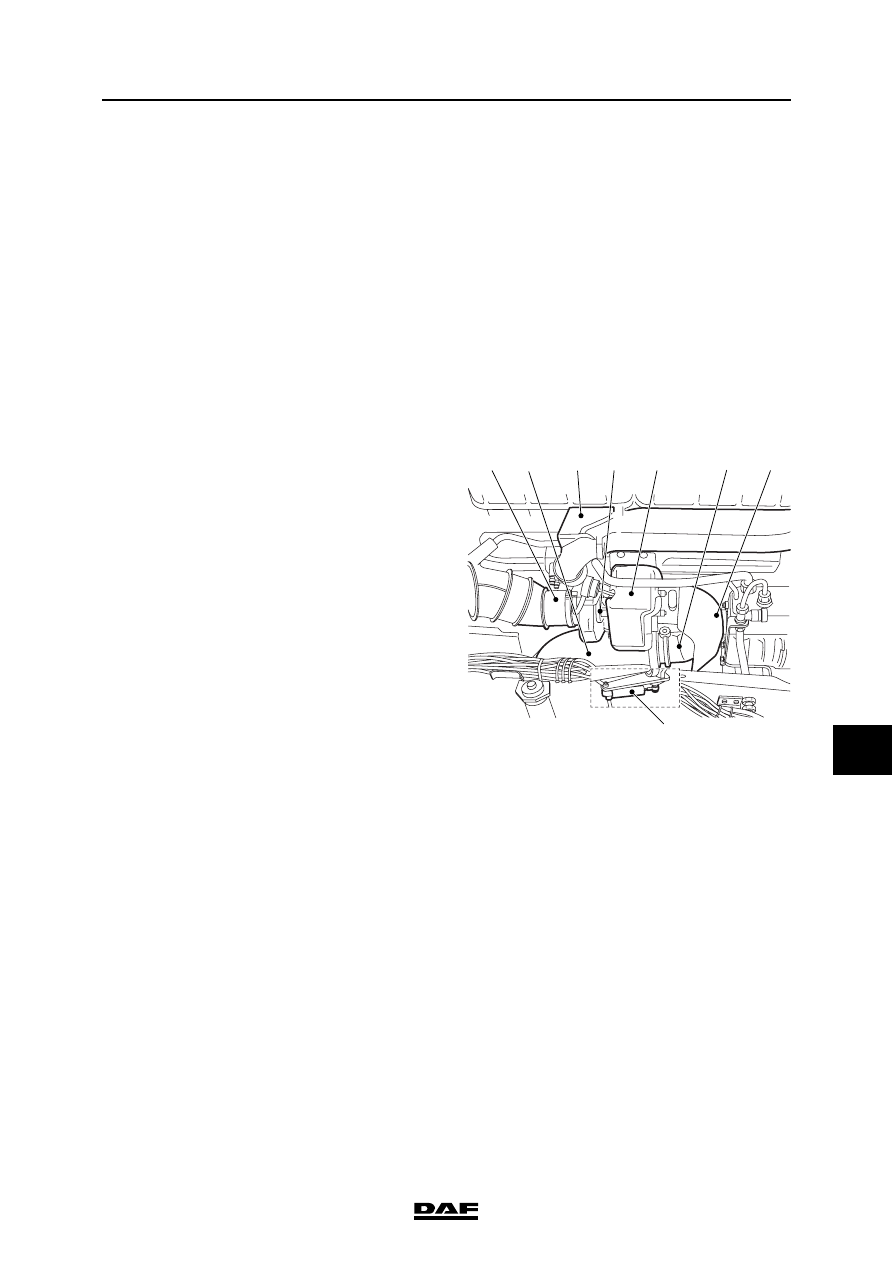
Removing the turbocharger
1.

Remove the noise insulation on the right-

hand side of the engine.

2.

Remove the inlet air pipe (1) and the flexible 

pipe (2).

3.

Remove the turbocharger heat shield (6) and 

the exhaust brake heat shield (5).

4.

Remove the turbocharger oil supply and 

discharge pipes from the engine block.

5.

Disconnect the air connection from the 

exhaust brake cylinder (8).

6.

Remove the exhaust brake (4) if necessary. 

(This can also be done after the 

turbocharger, including exhaust brake, has 

been rremoved from the exhaust manifold.)

If the exhaust brake stays attached, the 

clamping strip of the exhaust pipe (3) needs 

to be loosened.

7.

Remove the turbocharger (7) from the 

exhaust manifold flange.

Installing the turbocharger
Before installing the turbocharger, check the 

following:

-

The turbocharger shaft must rotate freely.

-

The turbocharger shaft must not run out of 

true.

-

The turbocharger shaft must have some 

radial clearance.

-

If applicable: movement of the wastegate.

-

Clean the sealing surfaces.

-

Apply a layer of Copaslip to the exhaust 

manifold studs.

-

Always use new gaskets during installation.

i400671

6

7

3

1

2

5

4

8

XE ENGINE INLET/EXHAUST SYSTEM

4-2

©

 200324

Removal and installation

9

CF65/75/85 series

4

1.

Fit (if removed) the exhaust brake (4).

2.

Install the turbocharger (7) on the exhaust 

manifold flange and tighten the attachment 

nuts to the specified torque. See "Technical 

data". If necessary, turn the two halves of the 

housing so that the oil and air pipes can be 

connected free of stress.

3.

Attach the exhaust pipe (3) to the clamping 

strip (4) on the exhaust brake.

4.

Fasten the air pipe of the exhaust brake 

cylinder (8).

5.

Fit the oil discharge pipe.

6.

Pour clean engine oil into the oil supply of the 

turbocharger and fit the oil supply pipe.

7.

Fit the air inlet ipie (1) and the flexible pipe 

(2).

8.

Install the heat shields (6 and 5) and tighten 

the attachment bolts to the specified torque. 

See "Technical data".

9.

Fit the sealing plate.

10. Always check the setting of the wastegate, 

see "Inspection and adjustment".

i400671

6

7

3

1

2

5

4

8

©

 200324

4-3

Removal and installation

XE ENGINE INLET/EXHAUST SYSTEM

CF65/75/85 series

4

9

4.2 REMOVAL AND INSTALLATION OF AIR COOLER

Note:

The removal and installation procedure of the 

air cooler allows for the presence of an air-

conditioning unit.

If such a unit is not present, the sections 

concerned can be skipped. Draining and filling of 

the air-conditioning system must only take place 

if the workshop is certified to do this.

Removing the air cooler
1.

Disconnect the earth lead from the battery 

terminal.

2.

Drain the engine coolant from the radiator.

3.

Disconnect the pipe from the bottom of the 

radiator.

4.

Carefully disconnect the air-conditioning 

compressor and condenser and hang them 

to one side (the system must not be opened).

5.

Disconnect the oil filler pipe and hang it to 

one side.

6.

Disconnect all coolant hoses (A, B and C) 

connected to the radiator.

M201031

E

A

C

A

B

D

XE ENGINE INLET/EXHAUST SYSTEM

4-4

©

 200324

Removal and installation

9

CF65/75/85 series

4

7.

Remove the left push/pull rod (H).

8.

Remove the rubber air inlet hoses (F).

9.

Remove the retaining screw (G) and turn the 

wind tunnel collar into the wind tunnel.

10. Remove the attachment nuts on the bottom 

of the radiator and remove the assembly.

Installing the air cooler
1.

Position the radiator assembly, carefully 

lower it into the chassis and fasten the 

radiator.

2.

Turn the wind tunnel collar back and position 

the retaining screw (G).

3.

Fit the rubber air inlet hoses (F).

4.

Fit the push/pull rods (H).

M201032

H

J

G

F

M201032

H

J

G

F


Content   ..  476  477  478  479   ..