DAF CF65, CF75, CF85 Series . Manual - part 463


  Index      DAF     DAF CF65, CF75, CF85 Series - service repair manual


Search            


Content   ..  461  462  463  464   ..


DAF CF65, CF75, CF85 Series . Manual - part 463


©

 200324

2-5

General

XE ENGINE FUEL SYSTEM

CF65/75/85 series

4

8

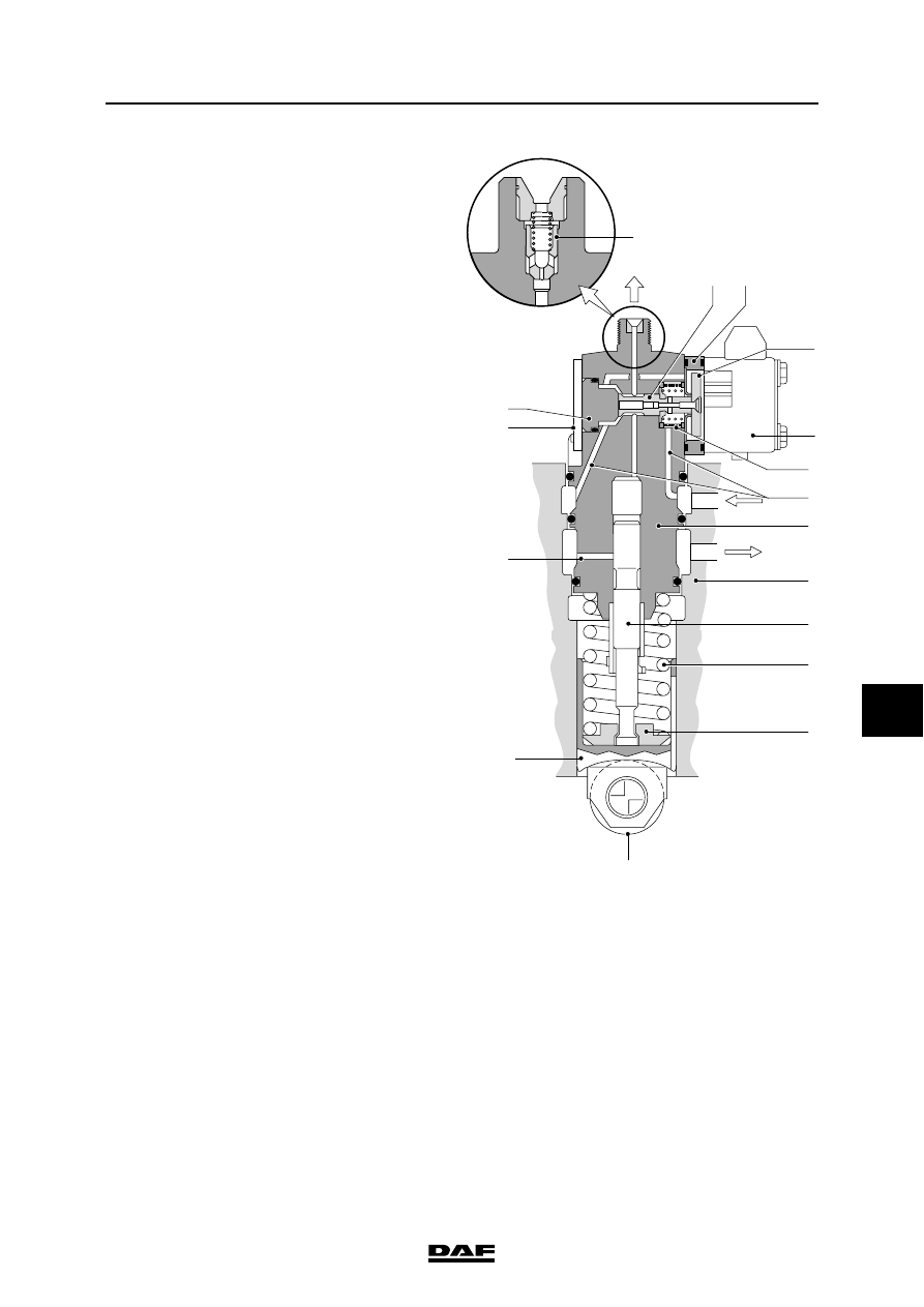
The valve (6), back plate (8) and the pump 

plunger (13) are located in the top of the pump 

unit.

These parts are lubricated by the fuel.

A roller (17), tappet (15) and a spring (14) with 

spring retainer (16) are situated on the bottom of 

the pump unit.

These parts are lubricated by the engine 

lubrication system.

The lower sealing ring on the pump unit 

separates the fuel system from the engine 

lubrication system.

A pressure valve (5) is fitted on the top of the 

pump unit.

The function of the pressure valve is to prevent 

the supply section from being interrupted by 

pressure peaks from the injector pipe.

The injection timing and the quantity of fuel to be 

injected are controlled by a solenoid valve (9) that 

consists of an electromagnet and valve (6) with 

back plate (8), via the electronic unit control.

If the solenoid valve (9) is not energised, the 

valve (6) is forced against the valve stop (4) by 

the force of the valve spring.

This creates a very small opening between the 

space above the pump plunger (13) and the 

supply ducts (2).

1

15

17

3

4

6

7

8

10

2

11

12

13

14

16

9

i 400434

5

XE ENGINE FUEL SYSTEM

2-6

©

 200324

General

8

CF65/75/85 series

4

If the solenoid valve (9) is energised by the 

electronic unit, the back plate (8) with the valve 

(6) will be attracted by the electromagnet due to 

the influence of the magnetic field.

The valve (6) closes the connection between the 

space above the pump plunger (13) and the 

supply ducts (2), causing pressure to build up in 

the space above the plunger (13).

This causes the injection.

The fuel will now flow via the fuel supply ducts (2) 

to the space above the pump plunger (13).

The valve (6) is not re-opened against the force 

of the magnet by the high-pressure in the high-

pressure area, as the forces in the valve (6) slot 

are balanced.

In other words, the left and right surfaces in the 

valve (6) slot are equal.

The time at which the valve (6) shuts depends on 

the injection timing calculated by the electronic 

unit.

The time that the valve (6) remains closed, and 

therefore the quantity of fuel injected, is also 

calculated by the electronic unit.

1

15

17

3

4

6

7

8

10

2

11

12

13

14

16

9

i 400435

5

©

 200324

2-7

General

XE ENGINE FUEL SYSTEM

CF65/75/85 series

4

8

2.3 DESCRIPTION OF COMPONENTS

Fuel lift pump with integrated primer pump
The fuel lift pump with integrated primer pump is 

fitted to the rear of the pump housing. The fuel lift 

pump section (1) is driven via the pulse plate (3) 

by the camshaft (4) in the pump housing.

The fuel lift pump (1) is a vane pump.

The vane pump consists of a stator (7) in which 

the rotor (8) with the vanes (9) can be found. The 

vanes (9) are forced against the surface of the 

stator (7) by the centrifugal force and two 

successive vanes form an enclosed space, the 

pump chamber. Due to the elliptically-shaped 

stator (7), with each revolution each pump 

chamber undergoes a volume increase, the 

suction stroke (angle A), a volume reduction and 

the compression stroke (angle B).

To achieve a good seal, the rear of the vanes are 

connected to the compression pipe of the pump. 

This forces the vanes against the stator with 

increased pressure, resulting in a good seal.

A pressure-relief valve (5) is fitted in the fuel lift 

pump to protect the fuel system against 

excessive fuel lift pump pressure caused by 

excessive flow resistance.

I400428

3

5

1

6

2

4

i 400433

8

9

7

A

B

XE ENGINE FUEL SYSTEM

2-8

©

 200324

General

8

CF65/75/85 series

4

Note:

Excessive fuel lift pump pressure may damage 

the fuel filter element and/or leakage may occur 

along seals.

A primer pump (2) is fitted for bleeding the fuel 

system. To operate the primer pump (2), it must 

first be loosened.

On the upward stroke, the volume above the 

priming pump piston is reduced. This causes the 

non-return valve (6) to close and the fuel flows 

along the piston seal to the bottom of the piston.

On the downward stroke, the volume below the 

priming pump piston is reduced. This forces the 

fuel via the fuel lift pump section to the fuel fine 

filter.

At the bottom of the fuel lift pump is a pressure-

relief area (10).

The pressure-relief area prevents fuel 

penetrating the lubrication system through 

sealing ring C and lubricating oil penetrating the 

fuel system through sealing ring D in the event of 

leakage.

A visual inspection for leaks is also possible with 

this.

I400432

1

10

D

C


Content   ..  461  462  463  464   ..