DAF CF65, CF75, CF85 Series . Manual - part 462
©
200324
2-1
General
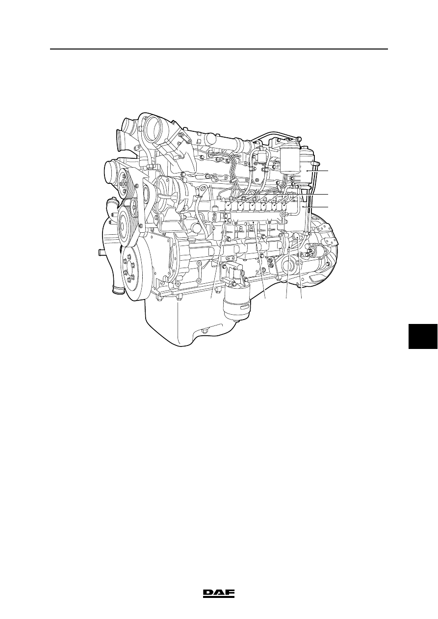
XE ENGINE FUEL SYSTEM
CF65/75/85 series
4
8
2. GENERAL
2.1 LOCATION OF COMPONENTS
1.
Pump units
2.
Pump housing
3.
Fuel fine filter
4.
Fuel lift pump
5.
UPEC electronic unit
6.
Primer pump
7.
Pressure relief valve
i4 00 683
3
5
7
2
6
4
1