DAF CF65, CF75, CF85 Series . Manual - part 455


  Index      DAF     DAF CF65, CF75, CF85 Series - service repair manual


Search            


Content   ..  453  454  455  456   ..


DAF CF65, CF75, CF85 Series . Manual - part 455


©

 200324

2-3

General

PE ENGINE INLET/EXHAUST SYSTEM

CF65/75/85 series

4

6

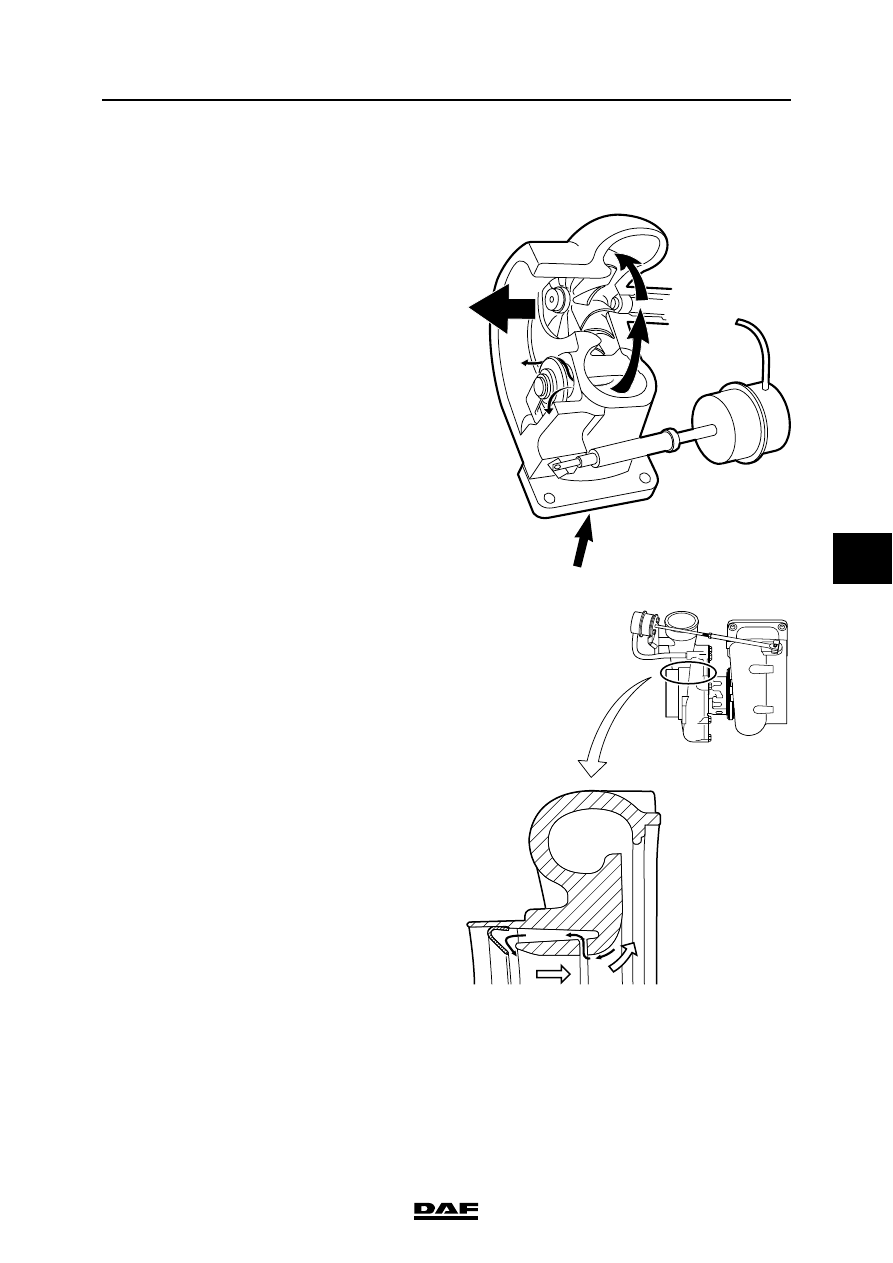
2.2 SYSTEM DESCRIPTION, TURBOCHARGER

Wastegate
To make the engine more responsive at lower 

engine speeds, a turbocharger is used that 

produces a better charge ratio at these speeds.

Without provision having been made for this, the 

boost pressure yielded by this turbocharger 

would be too high at maximum engine speeds. 

Use of a wastegate prevents this.

The turbocharger's compressor housing has an 

air coupling connected to a diaphragm. The boost 

pressure yielded by the turbocharger operates 

the diaphragm and the control rod connected to it.

The control rod operates a valve in the turbine 

housing.

The valve in the turbine housing is opened when 

the maximum pre-set pressure has been 

reached.

When the valve is opened, some of the exhaust 

gases will be discharged directly to the exhaust 

pipe rather than being used to propel the 

turbocharger's turbine wheel.

Compression housing by-pass
At higher boost pressures, the turbocharger 

compressor tends to allow this pressure to return 

to the intake underpressure area. To prevent this, 

the turbocharger's compression housing has 

been adapted.

This adaptation consists of bypass ducts and a 

stop plate.

Boost pressure attempting to return to the intake 

area will do so at the outer circumference of the 

compression housing.

The compression housing has been fitted with an 

air slot to force this pressure to flow back through 

special air ducts on the outside until it is arrested 

by the stop plate.

i400309

i 400212

PE ENGINE INLET/EXHAUST SYSTEM

2-4

©

 200324

General

6

CF65/75/85 series

4

©

 200324

3-1

Inspection and adjustment

PE ENGINE INLET/EXHAUST SYSTEM

CF65/75/85 series

4

6

3. INSPECTION AND ADJUSTMENT

3.1 INSPECTING AND ADJUSTING TURBOCHARGER WASTEGATE

1.

Remove the heat shield from the 

turbocharger.

2.

Remove the air supply connector (1) from 

the diaphragm housing (2).

3.

Remove the retaining clip (3) and remove the 

control rod (4) from the wastegate lever.

4.

Using a reducer valve, apply the specified 

adjusting pressure to the connection with the 

diaphragm housing (see "Technical data").

5.

Push the wastegate lever (5) fully to the left 

to close the wastegate valve.

6.

Adjust the length of the control rod (4), 

making sure it fits exactly onto the lever at 

the set pressure.

7.

Inspect the adjustment of the wastegate 

using the specified pressure. See "Technical 

data".

8.

Fit the retaining clip (3).

I400532

3

1

4

2

i 400214

4

3

2

1

0

5

4

2

PE ENGINE INLET/EXHAUST SYSTEM

3-2

©

 200324

Inspection and adjustment

6

CF65/75/85 series

4

3.2 CHECKING EXHAUST GAS BACK PRESSURE

Checking exhaust gas back pressure
1.

Remove the plug from the exhaust bracket 

and install a suitable coupling with a pipe. 

The first part of the pipe must be made of 

metal, to withstand the high temperatures.

2.

Connect a pressure gauge to the pipe, with a 

range of at least 0.1 - 0.2 bar (10 - 20 kPa).

Note:

Use an attenuated gauge to prevent 

excessive shaking of the gauge needle.

The engine brake must not be used during 

measurements.

This is to protect the pressure gauge.

3.

Measure the exhaust gas back pressure at 

full-load engine speed and compare the 

measurement to the specified value; see 

"Technical data".

i 400180


Content   ..  453  454  455  456   ..