DAF CF65, CF75, CF85 Series . Manual - part 426
©
200416
5-13
Removal and installation
CE ENGINE FUEL SYSTEM
ΧΦ65/75/85 series
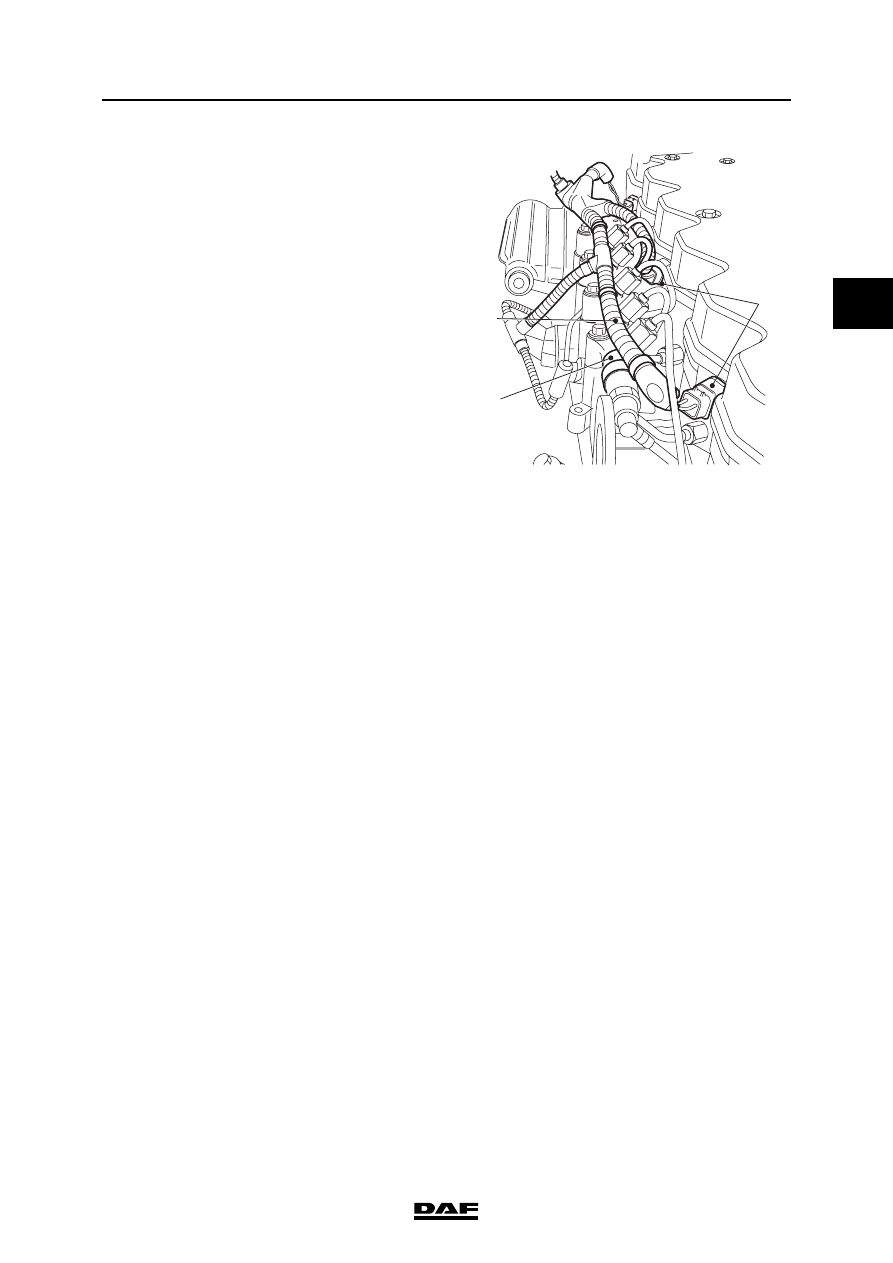
4
2
9.
Install the cable harness (3) to the fuel rail (2)
and secure it using cable ties.
10. Fit the connectors of the injectors (1) in the
valve sleeve.
11. If it has been removed, fit the plug of the inlet
air temperature/boost pressure sensor to the
sensor.
12. Fit the connector of the fuel rail pressure
sensor.
13. Start the engine and check the fuel system
for leaks.
i400809
3
1
2