DAF CF65, CF75, CF85 Series . Manual - part 424
©
200416
5-5
Removal and installation
CE ENGINE FUEL SYSTEM
ΧΦ65/75/85 series
4
2
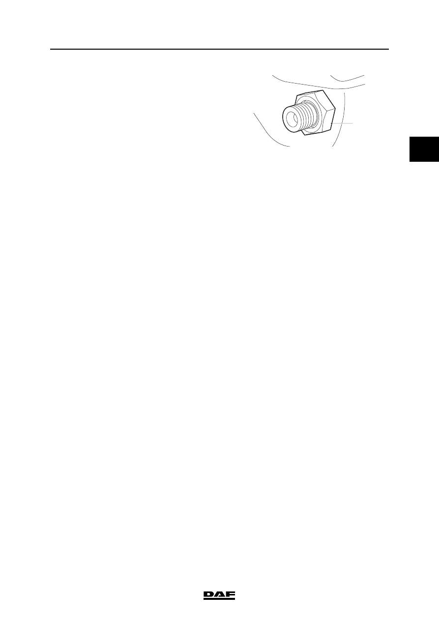
5.
Install the nut (1) and tighten it to the
specified torque. See "Technical data".
6.
If the fuel rail was removed, re-fit it.
7.
Fit the injector pipes.
8.
Start the engine to bleed the high-pressure
section of the fuel system and inspect the
fuel system for leaks.
1
i400486