DAF CF65, CF75, CF85 Series . Manual - part 398


  Index      DAF     DAF CF65, CF75, CF85 Series - service repair manual


Search            


Content   ..  396  397  398  399   ..


DAF CF65, CF75, CF85 Series . Manual - part 398


3

CF65/75/85 series

Removal and installation

AS TRONIC GEARBOX

4-11

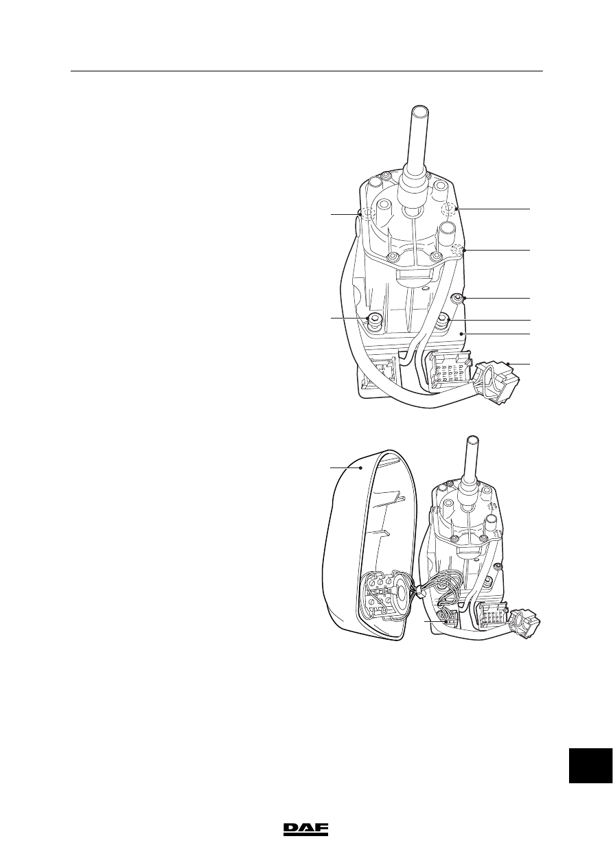
Fitting operating unit assembly
1.

Install the bottom plate (9) with the gear
lever unit and fit connector 6.

V300686

6

9

8

7

8

7

7

7

2.

Connect connector 4 and fit the cover (5)
with the selector switch.

Note:
Take care that the locking mechanism that
is fitted to prevent the bottom plate from
rotating relative to the gear lever does not
break during installation.

V300685

4

5

14

ᓻ 200337

3

AS TRONIC GEARBOX

Removal and installation

CF65/75/85 series

4-12

3.

Install the gear lever knob and the bottom
plate. Fit the attachment bolt and position
the cover (1).

4.

Fit the selector switch knob. Fit the
attachment bolt and the cap (2).

V300683

1

2

R

N

D

S

M A

14

ᓻ 200337

3

CF65/75/85 series

Removal and installation

AS TRONIC GEARBOX

4-13

4.4 REMOVAL AND INSTALLATION, DRIVE FLANGE

Removing drive flange
1.

Remove the prop shaft from the gearbox
flange and hang it on the chassis.

2.

Hold the drive flange in place with the
special tool (DAF No. 0484977).

3.

Remove the attachment bolts from the drive
flange.

4.

Remove the bolts and locking plate with
seal from the drive flange.

5.

Note:
Measure and make a note of the distance
from the drive flange to the shaft. The same
distance must be observed when the drive
flange is reinstalled.

Remove the drive flange and O-ring using a
commercially available puller.

Installing drive flange
1.

Lightly oil the sealing ring in the bearing
cover.

2.

Heat the drive flange to 70

°C. Slide it as far

as possible onto the output shaft. Use the
locking plate and two standard bolts
(M12x75) to pull the drive flange further
onto the shaft.

3.

Remove the standard bolts and measure
whether the drive flange has reached the
correct position on the output shaft.

4.

Fit a new O-ring into the recess between
the output shaft and the drive flange.

5.

Hold the drive flange in place with the
special tool (DAF No. 0484977).

6.

Note:
Bolts that will be re-used must be cleaned
and lightly oiled.

Tighten the attachment bolts to the
specified torque. See “Technical data”.

7.

Attach the prop shaft.

V300449

14

ᓻ 200337

3

AS TRONIC GEARBOX

Removal and installation

CF65/75/85 series

4-14

4.5 REMOVAL AND INSTALLATION, OUTPUT SHAFT OIL SEAL

Removing the output shaft oil seal
1.

Remove the prop shaft from the gearbox
flange and hang it on the chassis.

2.

Remove the drive flange.

3.

Drill two holes into the external cover of the
oil seal and turn the special tool
(DAF No. 0484899) into the oil seal. Then
pull the oil seal out of the bearing cover
using the special tool (DAF No. 0694928).

Installing the output shaft oil seal
1.

Apply methylated spirit to the outer
circumference of the oil seal. Apply a little
grease to the sealing lip.

2.

Fit the oil seal into the bearing cover using
the special tool (DAF No. 1453146 in
combination with 1453148).

3.

Fit the drive flange.

4.

Attach the prop shaft.

14

ᓻ 200337


Content   ..  396  397  398  399   ..