DAF CF65, CF75, CF85 Series . Manual - part 312


  Index      DAF     DAF CF65, CF75, CF85 Series - service repair manual


Search            


Content   ..  310  311  312  313   ..


DAF CF65, CF75, CF85 Series . Manual - part 312


3

CF65/75/85 series

Description of components

GEARBOX - PNEUMATIC SECTION

2-3

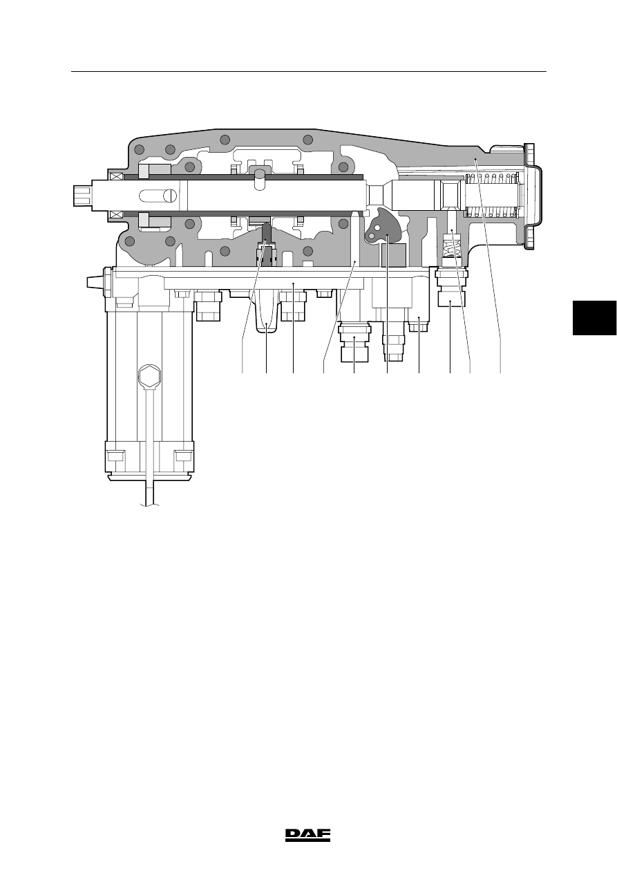
Sectional drawing of integrated air
distribution block:

V300868

1

3

4

6

8

5

7

9

10

2

1.

Neutral position valve

2.

Neutral position valve attachment pin

3.

Air distribution block

4.

Neutral switch

5.

Neutral position valve attachment pin

6.

Locking cylinder

7.

Locking cylinder lever

8.

Reversing switch

9.

Reversing switch attachment pin

10. Selector housing

4

ᓻ 200337

3

GEARBOX - PNEUMATIC SECTION

Description of components

CF65/75/85 series

2-4

2.2 NEUTRAL POSITION VALVE

Situation with separate air distribution block:

V300140

Pneumatic symbol

Connection

point

Function

1

Supply

21

Cut-in pressure,
range-change switch

22

Plugged

Position

Function

N

Gearbox selector shaft in
neutral

V

Gearbox selector shaft
engaged

N

V

1

21

22

V300160

4

ᓻ 200337

3

CF65/75/85 series

Description of components

GEARBOX - PNEUMATIC SECTION

2-5

Operation
Gearbox in neutral:
In the neutral position, thrust pin A will be
pushed into a recess in the selector shaft by
means of the air pressure coming from
connection 1 and a bore hole through sealing
pin B. Sealing pin B will provide a spring-loaded
seal on seat C. The air flow can now leave the
valve via connection 21 and subsequently
operate the range cylinder through the
electropneumatic valve.

W 3 02 098

21

1

3

22

A

B

C

Gearbox engaged:
When a gear has been engaged, the selector
shaft will push the thrust pin A up against
sealing pin B. This closes off the bore hole in
this pin and causes the pin to be lifted of seat C
against the spring pressure. The air pressure in
the gear engaging cylinder can now flow back to
the neutral valve via the electropneumatic valve
and leave the valve housing through the bleed
opening (3).

W 3 02 102

21

1

3

22

A

B

C

4

ᓻ 200337

3

GEARBOX - PNEUMATIC SECTION

Description of components

CF65/75/85 series

2-6

Situation with integrated air distribution
block

V300862

Pneumatic symbol

Connection

point

Function

1

Supply

21

Cut-in pressure,
range-change switch

Position

Function

N

Gearbox selector shaft in
neutral

V

Gearbox selector shaft
engaged

 V300863

V

21

1

N

4

ᓻ 200337


Content   ..  310  311  312  313   ..