DAF CF65, CF75, CF85 Series . Manual - part 252
©
200324
4-11
Removal and installation
XE ENGINE
CF65/75/85 series
2
8
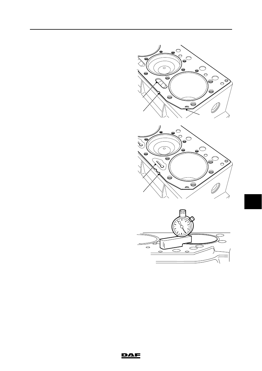
Note:
Note the markings (2, 5) on the cylinder head
gasket to be replaced and use the same gasket
when fitting. The cylinder head gaskets can also
be recognised from the coolant holes (3, 4).
22. Remove any remnants of gasket from the
cylinder heads and the cylinder block.
23. Check the sealing surfaces of the cylinder
block.
24. Check the threaded holes in the cylinder
block for damage and cracking.
25. Using the special tool (DAF no. 0694795),
check that the amount the cylinder liner
protrudes above the cylinder block is within
tolerance. See "Technical data".
26. Check the cylinder head. See "Inspection
and adjustment".
Installing the cylinder heads
1.
Clean the threaded holes in the cylinder
block using a screw tap.
Note:
Threaded holes not properly cleaned may
lead to too low a pre-tension of the cylinder
head bolts, causing leakage.
2.
Clean and degrease the sealing surfaces of
the cylinder heads and the cylinder block.
3.
Insert both guide pins (DAF no. 0694912)
into the threaded holes of the cylinder block.
M201278
3
2
1
4
5
M2 00 100