DAF CF65, CF75, CF85 Series . Manual - part 248


  Index      DAF     DAF CF65, CF75, CF85 Series - service repair manual


Search            


Content   ..  246  247  248  249   ..


DAF CF65, CF75, CF85 Series . Manual - part 248


©

 200324

3-7

Inspection and adjustment

XE ENGINE

CF65/75/85 series

2

8

3.5 INSPECTION AND ADJUSTMENT, V-BELT TENSION

Inspecting the V-belt tension
1.

Check the V-belt tension of the air 

conditioning compressor drive using the 

Krikit I, special tool (DAF no. 1240442).

Check the V-belt tension of the FAX model 

steering pump drive using the Krikit II, 

special tool (DAF no. 1240443).

2.

Set the gauge to zero by depressing the 

measuring arm (1).

3.

Place the belt tension gauge on the V-belt, 

halfway between the two pulleys.

4.

Slowly depress the V-belt by means of the 

belt-tension gauge until a click is heard. 

Then remove the belt tension gauge 

carefully. Take care not to let the measuring 

arm move. 

5.

Take the reading as indicated by the position 

of the measuring arm in relation to the scale. 

Compare this reading with the 

recommended pre-tension, see "Technical 

data".

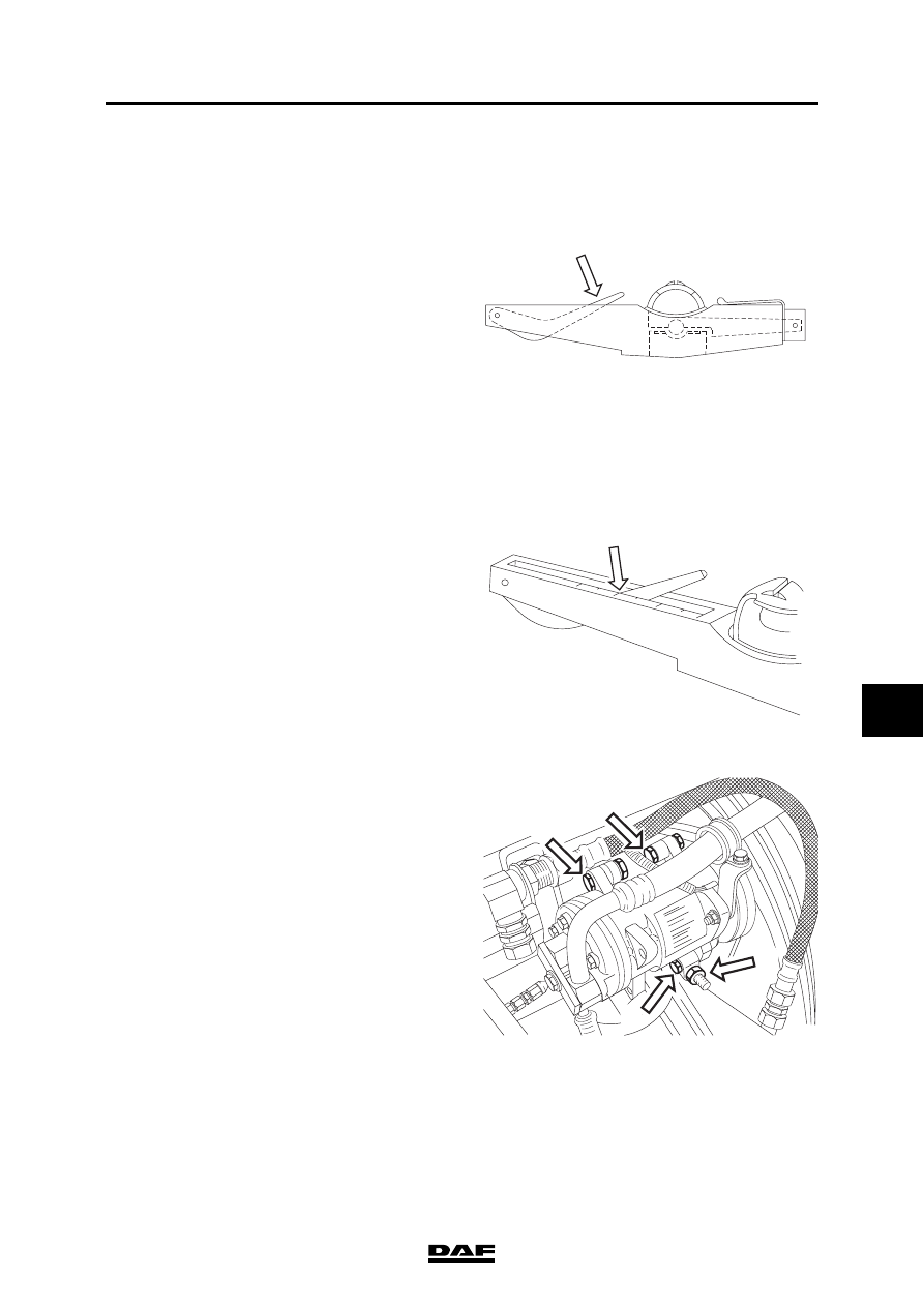
Adjust V-belt tension of air conditioning 
compressor drive
1.

Slacken the upper attachment bolt (1) of the 

compressor.

2.

Slacken the lower attachment bolt (2) of the 

compressor.

3.

Loosen the attachment bolt from the 

threaded spindle which is attached to the 

coolant pump.

4.

Shift the compressor using the lock nuts (3) 

until the correct V-belt tension is achieved, 

see "Technical data".

1

M2061

M2062

M2041

3

2

1

1

XE ENGINE

3-8

©

 200324

Inspection and adjustment

8

CF65/75/85 series

2

Adjusting V-belt tension of FAX model 
steering pump
1.

Slacken the central bolt (1) of the tension 

roller.

2.

Turn the adjusting bolt (2) until the V-belt 

tension is correct, see "Technical data".

3.

Tighten the central bolt (1) to the specified 

tightening torque, see "Technical data".

©

 200324

3-9

Inspection and adjustment

XE ENGINE

CF65/75/85 series

2

8

3.6 INSPECTION, FLYWHEEL

1.

If the flywheel shows cracks on the abutting 

surface with the clutch plate, the flywheel 

may be ground down, provided that the 

cracks are not within 5 mm of the inner rim.

2.

The flywheel has an indicator groove for 

inspection purposes.

3.

Grinding down is allowed until the indicator 

groove is no longer visible. This means that 

a maximum of 2 mm may be ground down.

Checking flywheel run-out
1.

Clean the flywheel.

2.

Place a metal strip on the edge of the 

flywheel housing to fit a dial gauge.

3.

Place the dial gauge on the metal strip.

4.

Place the stylus of the dial gauge at the 

specified distance. See "Technical data".

5.

Set the dial gauge to "0".

6.

Use the special tool (DAF no. 1310477) to 

crank the engine through 360

°, and measure 

the maximum dial gauge reading. Compare 

this reading with the technical data. See 

"Technical data".

5 mm

2 mm

5 mm

M2 00 033

M200230

XE ENGINE

3-10

©

 200324

Inspection and adjustment

8

CF65/75/85 series

2

3.7 INSPECTION, CYLINDER HEAD

1.

Check the sealing plugs of the cylinder head 

for leaks. If necessary, pressure-test the 

cylinder head.

2.

Inspect the cylinder head for damage to the 

sealing surface and any cracks. If necessary, 

have the cylinder head levelled. See 

"Technical data".


Content   ..  246  247  248  249   ..