DAF CF65, CF75, CF85 Series . Manual - part 246


  Index      DAF     DAF CF65, CF75, CF85 Series - service repair manual


Search            


Content   ..  244  245  246  247   ..


DAF CF65, CF75, CF85 Series . Manual - part 246


©

 200324

2-5

General

XE ENGINE

CF65/75/85 series

2

8

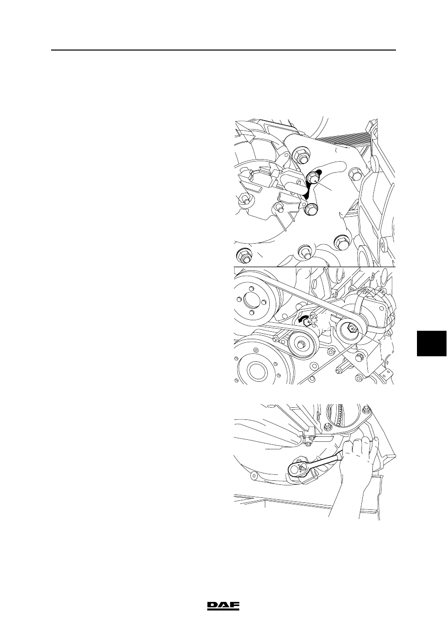
2.5 CRANKING THE ENGINE

Crank using the automatic poly-V-belt 
tensioner
1.

Put an M8 x 90 bolt (A) into the rear of the 

automatic tensioner via the opening at the 

rear of the alternator bracket. 

2.

Screw the bolt in until the automatic 

tensioner locks.

3.

Place a spanner on the nut (C) on the 

alternator and turn the engine clockwise.

Note:

Turning the nut anti-clockwise may cause the 

alternator nut to work loose.

If the tensioner slips while cranking, it can be pre-

tensioned a little by turning the automatic 

tensioner anti-clockwise (B) whilst securing the 

bolt (A).

Cranking using the flywheel
1.

Place the special tool (DAF no. 1310477) on 

the opening at the bottom of the flywheel 

housing such that the pinion engages the 

starter ring gear.

2.

Turn the crankshaft clockwise as seen from 

the timing gear end (this corresponds to the 

direction of rotation of the engine).

B

C

A

M201273

M201187

XE ENGINE

2-6

©

 200324

General

8

CF65/75/85 series

2

©

 200324

3-1

Inspection and adjustment

XE ENGINE

CF65/75/85 series

2

8

3. INSPECTION AND ADJUSTMENT

3.1 INSPECTION AND ADJUSTMENT, VALVE GEAR BRIDGES

1.

Remove the valve covers. See "Removal 

and installation".

2.

Remove the DEB or the lubricating oil strip 

(depending on version).

3.

Remove the entire rocker seat. Mark the 

position to enable reinstallation in the same 

position.

Note:

In engines with a DEB, the bridges of the inlet and 

exhaust valves are different. 

Note:

In engines without a DEB, the bridges of the inlet 

and exhaust valves are the same.

Exhaust bridge with DEB

i 400162

Exhaust bridge without DEB

i 400161

XE ENGINE

3-2

©

 200324

Inspection and adjustment

8

CF65/75/85 series

2

4.

Remove the bridge from the valves and 

place it in a vice.

}

Loosening and tightening the lock 

nuts (B) of the bridges may cause 

severe damage to the valve guides if 

the bridge is fitted over the valves.

5.

Slacken the lock nut (B).

6.

Reposition the bridge in the same position in 

the engine over the valves.

7.

Firmly press on the bridge centre (above the 

guide pin) with your thumb and hand-tighten 

the adjusting screw (A) until the bridge starts 

to move (the adjusting screw (A) now 

touches the valve).

8.

Turn the adjusting screw (A) through another 

90

° and carefully remove the bridge from the 

valves.

9.

Place the bridge in a vice and tighten the lock 

nut (B) to the specified torque without turning 

the adjusting screw (A). See "Technical 

data".

Note:

Loosening and tightening the lock nuts (B) of 

the bridges may cause severe damage to the 

valve guides if the bridge is fitted over the 

valves.

10. Reposition the bridge over the valves.

11. Fit the rocker seat.

12. Fit the DEB or the lubricating oil strip 

(depending on version). Fit the lubricating oil 

strip in such a way that the mark "cyl. 1/4" is 

located on cylinder 1 or cylinder 4.

13. Set the valve clearance and, if applicable, 

the DEB clearance (see "Technical data").

14. Fit the valve covers. See "Removal and 

installation".

i 400234

A

B

M200548


Content   ..  244  245  246  247   ..