DAF CF65, CF75, CF85 Series . Manual - part 237


  Index      DAF     DAF CF65, CF75, CF85 Series - service repair manual


Search            


Content   ..  235  236  237  238   ..


DAF CF65, CF75, CF85 Series . Manual - part 237


©

 200324

5-5

Removal and installation

PE ENGINE COOLING SYSTEM

CF65/75/85 series

2

6

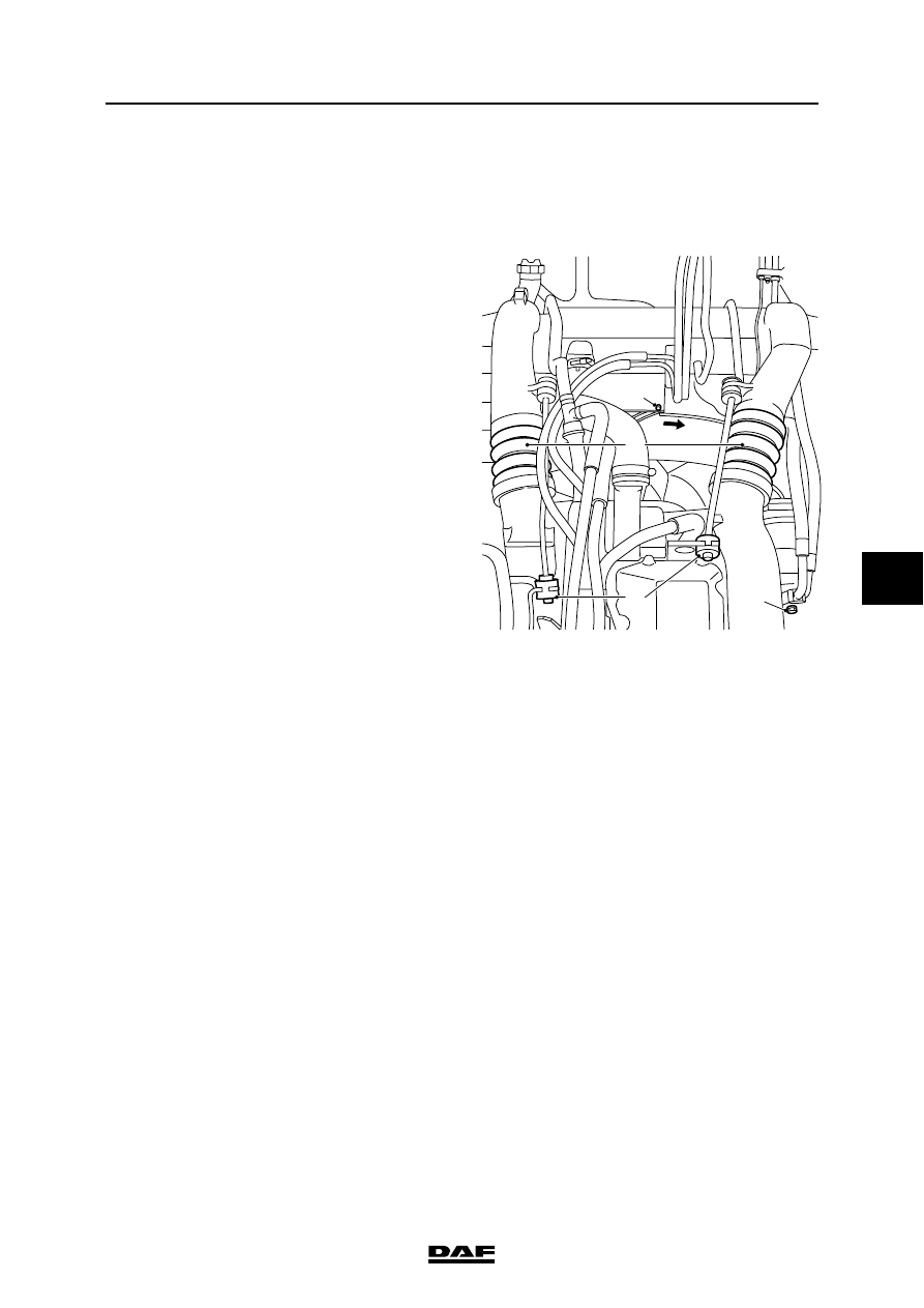
5.4 REMOVAL AND INSTALLATION, VISCOUS FAN CLUTCH

Removing the viscous fan clutch
1.

Remove the front engine encapsulation.

2.

Loosen the wind tunnel collar by removing 

the retaining screw (G) and turn the wind 

tunnel collar towards the radiator.

3.

Remove the fan from the viscous fan clutch 

and place it temporarily in the wind tunnel.

Note:

The viscous fan must always be stored 

vertically.

4.

Remove the viscous fan clutch from the drive 

flange.

Installing the viscous fan clutch
1.

Install the viscous fan clutch on the drive 

flange and tighten the attachment bolts to the 

specified torque. See "Technical data".

2.

Fit the fan to the viscous fan clutch. Tighten 

the attachment nuts to the specified 

tightening torque. See "Technical data".

3.

Turn the wind tunnel collar towards the 

engine and check whether it is installed 

properly all round in its lock. Fit the locking 

screw (G).

4.

Fit the front engine encapsulation.

M201032

H

J

G

F

PE ENGINE COOLING SYSTEM

5-6

©

 200324

Removal and installation

6

CF65/75/85 series

2

5.5 REMOVAL AND INSTALLATION, RADIATOR UNIT

Removing the radiator unit
1.

Drain the coolant.

2.

Disconnect the torque rods (H).

3.

Remove the air inlet hoses (F) between the 

engine and the air cooler.

4.

Remove the locking screws from the wind 

tunnel collar (G) and turn the latter inwards.

5.

Disconnect the air-conditioning condenser (if 

fitted) including accessories from the radiator 

unit.

6.

Disconnect the air-conditioning compressor 

from the engine and carefully put the 

complete air-conditioning system to one 

side.

7.

Disconnect the rubber hoses from the 

radiator unit.

8.

Disconnect the oil filler pipe from the radiator 

unit.

9.

Disconnect the radiator unit and remove the 

assembly with the air cooler.

Installing the radiator unit
1.

Fit the radiator unit together with the air 

cooler.

2.

Fit the oil filler pipe to the radiator unit.

3.

Fit all rubber hoses to the radiator unit.

4.

Fit the air-conditioning condenser (if present) 

including accessories to the radiator unit.

5.

Fit the air-conditioning compressor to the 

engine.

6.

Turn the wind tunnel collar (G) outwards and 

fit the locking screws.

7.

Remove the air inlet hoses (F) between the 

engine and the air cooler.

8.

Fit the torque rods (H).

9.

Fill the cooling system.

M201032

H

J

G

F

M201032

H

J

G

F

©

 200324

6-1

Draining and filling

PE ENGINE COOLING SYSTEM

CF65/75/85 series

2

6

6. DRAINING AND FILLING

6.1 DRAINING, FILLING AND BLEEDING THE COOLING SYSTEM

}

In order to avoid damaging the 

cylinder block, do not top up a warm 

engine with cold coolant. Coolant is 

a toxic fluid and must be handled 

with care. Protect skin and eyes. 

Coolant is harmful to the 

environment; after use, it should be 

processed as industrial chemical 

waste. When the coolant is hot, there 

is overpressure in the cooling 

system. When removing the filler 

cap, allow the overpressure to 

escape by first loosening the filler 

cap one turn.

Draining the cooling system
1.

Turn the heater control knob to the 

"warmest" temperature setting. As a result, 

the heater valve will be fully opened.

2.

Remove the cooling system filler cap.

3.

Collect the coolant. Position suitable 

containers under the drain points.

4.

Drain the cooling system via the drain tap (A) 

on the side of the cylinder block and via drain 

plug B underneath the radiator and plug C on 

the lower side of the oil cooler.

5.

If an integrated retarder has been fitted 

remove the coolant hose (D) from the oil 

cooler and drain the remaining coolant.

6.

Flush the cooling system.

7.

Close the engine drain tap (A) and install the 

drain plugs (B and C) on the lower side of the 

radiator and on the oil cooler.

M2097

A

B

C

D

M2077

PE ENGINE COOLING SYSTEM

6-2

©

 200324

Draining and filling

6

CF65/75/85 series

2

Filling and bleeding cooling system
1.

Turn the heater temperature control knob in 

the cab to the "warmest" setting.

2.

With the cab in the driving position, fill the 

cooling system with the specified coolant up 

to the edge of the filler opening.

3.

Run the engine for several minutes.

Note:

The cooling system is auto-bleeding.

4.

Ensure that the air bleed pipe from the 

thermostat housing to the header tank is not 

twisted or pinched.

5.

Check the coolant level, and top up with 

coolant if necessary.

If the vehicle is equipped with a water/air cab 
heater.
1.

Run the engine at idling speed.

2.

Switch on the cab heater using the rocker 

switch on the dashboard.

3.

Turn the heater temperature control knob in 

the cab to the "warmest" setting.

4.

Switch on the heater fan.

5.

Set the rocker switch on the thermostat in the 

cab to position 1.

Note:

Combustion will start after approximately 

one minute.

6.

Allow the cab heater to operate for 

approximately 15 minutes.


Content   ..  235  236  237  238   ..