DAF CF65, CF75, CF85 Series . Manual - part 228


  Index      DAF     DAF CF65, CF75, CF85 Series - service repair manual


Search            


Content   ..  226  227  228  229   ..


DAF CF65, CF75, CF85 Series . Manual - part 228


©

 200324

4-27

Removal and installation

PE ENGINE

CF65/75/85 series

2

5

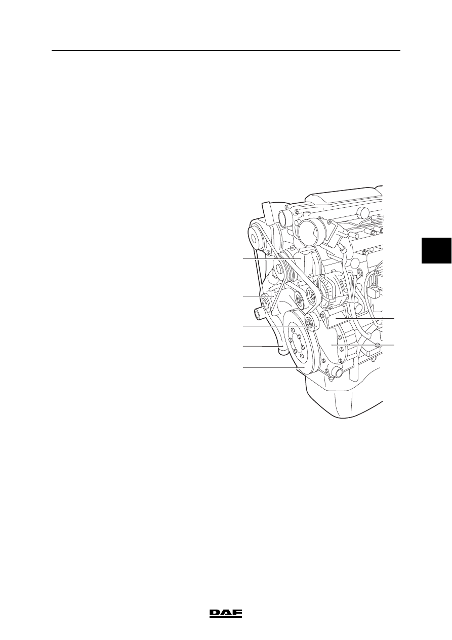
4.21 REMOVAL AND INSTALLATION, TIMING COVER

}

When the engine or parts thereof are 

opened, dirt may enter. This may 

cause serious damage to the engine. 

Therefore, the engine should be 

cleaned thoroughly before any parts 

are opened.

Removing the timing cover
1.

Drain the coolant.

2.

Remove the air conditioning compressor 

V-belt and the tensioner (2), if fitted.

3.

Remove the poly-V-belt.

4.

Remove the electrical connections of the 

alternator and remove the alternator bracket 

(6) and alternator.

5.

Remove the guide roller (3).

6.

Remove the pulley (1) from the coolant 

pump.

7.

Remove the vibration damper (5).

8.

Remove the vibration damper hub using the 

special tool (DAF no. 1329472).

9.

Loosen the coolant pipe (4) until it does not 

impede removal of the timing cover.

10. Mark the position of the various attachment 

bolts and studs.

11. Remove the attachment bolts from the timing 

cover (7) and remove the cover.

12. Remove any remnants of gasket. Clean and 

inspect the sealing surfaces, dowels and 

locating holes.

13. Remove the oil seal from the timing cover.

1

2

3

4

5

6

7

M2 01 282

PE ENGINE

4-28

©

 200324

Removal and installation

5

CF65/75/85 series

2

Installing the timing cover
1.

Use three studs to position the gasket. Fit the 

new gasket.

2.

Fit the timing cover (7).

3.

Install the attachment bolts and tighten them 

to the specified torque. See "Technical data".

4.

Remove the three studs used to position the 

gasket and replace them with the remaining 

attachment bolts.

5.

Fit new O-rings to the coolant pipe (4) and 

fit it.

6.

Fit the timing cover seal.

7.

Fit the vibration damper hub.

8.

Fit the vibration damper (5).

9.

Fit the coolant pump pulley.

10. Fit the poly-V-belt.

11. Fit the tensioner (2) and the air conditioning 

compressor V-belt.

12. Fit the alternator bracket (6) and alternator 

and connect the electrical wiring to the 

alternator.

©

 200324

4-29

Removal and installation

PE ENGINE

CF65/75/85 series

2

5

4.22 REMOVAL AND INSTALLATION, TIMING COVER SEAL

Removing the timing cover seal
1.

Remove the poly-V-belt.

2.

Remove the vibration damper.

3.

Remove the vibration damper hub.

4.

Remove the timing cover seal by using the 

special tool (DAF no. 1329458) to pull the 

seal out of the cover.

Installing the timing cover seal
1.

Clean and check the seal recess in the timing 

cover. Even minimal damage may cause a 

leak.

Note:

If a shim was fitted in the seal recess, it must 

be re-fitted.

2.

Use the special tool (DAF no. 1329446) to 

install the dry sealing ring and the thrust 

piece in the recess of the timing cover.

3.

Remove the special tool.

4.

Fit the vibration damper hub.

5.

Install the vibration damper.

6.

Fit the poly-V-belt.

M200971

W264003

PE ENGINE

4-30

©

 200324

Removal and installation

5

CF65/75/85 series

2

4.23 REMOVAL AND INSTALLATION, TIMING GEARS

Removing the timing gear
1.

Remove the valve covers.

2.

Position cylinder 1 at top dead centre (TDC 

on the flywheel, cylinder 6 in overlap 

position).

3.

Remove the timing cover.

Note:

It is possible that the marks on the idler gear 

are not exactly opposite the camshaft and 

crankshaft gear wheel.

Removing the idler gear
1.

Remove the attachment bolt (9) and the axial 

thrust washer.

2.

Remove the idler gear (3).

Removing the pump housing camshaft gear
1.

Remove the attachment bolt (10) of the 

pump housing camshaft gear (5).

2.

Remove the attachment bolt (9) and the axial 

thrust washer from the idler gear (3).

3.

Remove the idler gear.

4.

Remove the pump housing camshaft gear 

using a commercially available puller.

Removing the camshaft gear
1.

Remove the attachment bolt (11) of the 

camshaft gear (2).

2.

Remove the attachment bolt (9) and the axial 

thrust washer from the idler gear (3).

3.

Remove the idler gear.

4.

Remove the camshaft gear using a 

commercially available puller.

M201185

7

6

1

8

9 3

10

5

11 2

12 4

M201171


Content   ..  226  227  228  229   ..