DAF CF65, CF75, CF85 Series . Manual - part 147


  Index      DAF     DAF CF65, CF75, CF85 Series - service repair manual


Search            


Content   ..  145  146  147  148   ..


DAF CF65, CF75, CF85 Series . Manual - part 147


©

 200346

4-9

Removal and installation

CAB TILTING MECHANISM

ΧΦ65/75/85 series

1

6

4.4 REMOVAL AND INSTALLATION, CAB TILTING PUMP TWO-WAY VALVE

Note:
-

Use a repair kit to replace the two-way valve.

-

Disassembling any other parts of the tilting 
pump than those described in this chapter is 
not permitted. A defective cab tilting 
mechanism is often the result of incorrect 
disassembly and/or assembly of the cab 
tilting pump.

-

Clean the outside of the cab tilting pump.

-

Work in a clean environment.

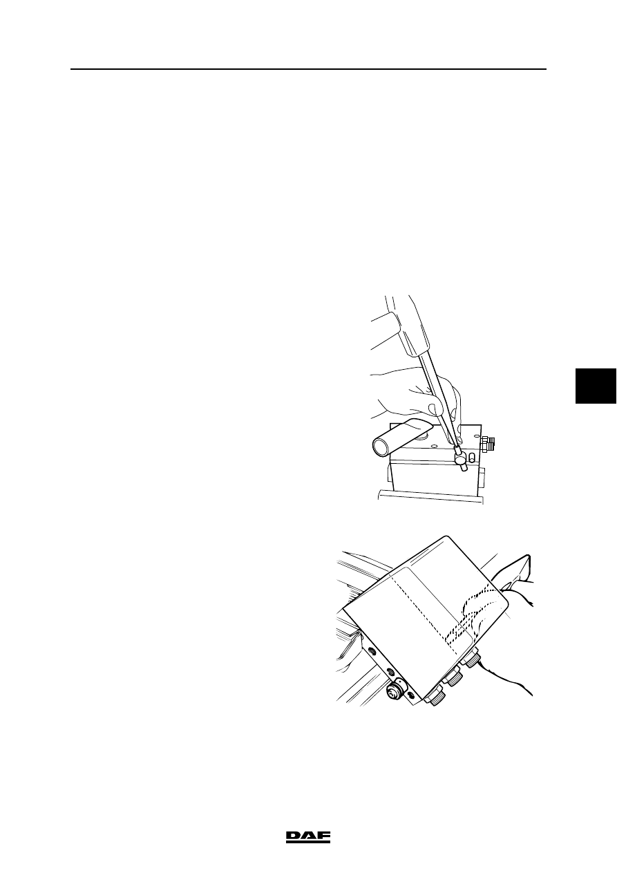
Removing cab tilting pump two-way valve
1.

Remove the cab tilting pump.

2.

Tap the notched pin out of the two-way valve 
and remove the steel ring. Remove the O-
ring from the steel ring.

3.

Secure the pump housing in a vice as shown 
in the adjacent figure and carefully tap the 
two-way valve with the sealing plug out of the 
housing. Note: Mark the position of the two-
way valve in the pump housing so that the 
new two-way valve can be mounted in the 
right position.

K1 01 340

K1 01 496

CAB TILTING MECHANISM

4-10

©

 200346

Removal and installation

6

ΧΦ65/75/85 series

1

4.

Take the pump housing from the vice and 
remove the inlet ball. 

5.

Remove the O-ring and the Teflon ring from 
the pump housing.

Installing cab tilting pump two-way valve

Note:
-

When the two-way valve is installed, observe 
the correct position of the openings in 
relation to the connections.

-

After assembly of the two-way valve, the 
pressure limiting valve must be checked/
adjusted. See "Inspection and adjustment".

1.

Fit the new inlet ball into the pump housing.

2.

Apply a little oil to the O-rings of the new two-
way valve only. 

3.

Fit the two-way valve and the sealing plug in 
the housing. Note: Make sure the openings 
in the two-way valve and the connections in 
the pump housing are well positioned.

4.

Fit the new O-ring and the Teflon ring in the 
pump housing.

K1 01 497

k100144

©

 200346

4-11

Removal and installation

CAB TILTING MECHANISM

ΧΦ65/75/85 series

1

6

5.

Fit the new O-ring in the steel ring. Fit the 
steel ring onto the two-way valve and tap the 
new notched pin into the two-way valve.

K1 01 340

CAB TILTING MECHANISM

4-12

©

 200346

Removal and installation

6

ΧΦ65/75/85 series

1


Content   ..  145  146  147  148   ..