Content .. 1109 1110 1111 1112 ..
DAF CF65, CF75, CF85 Series . Manual - part 1111
©
200448
2-1
Inspection and adjustment
FAG
ΧΦ65/75/85 series
9
7
2. INSPECTION AND ADJUSTMENT
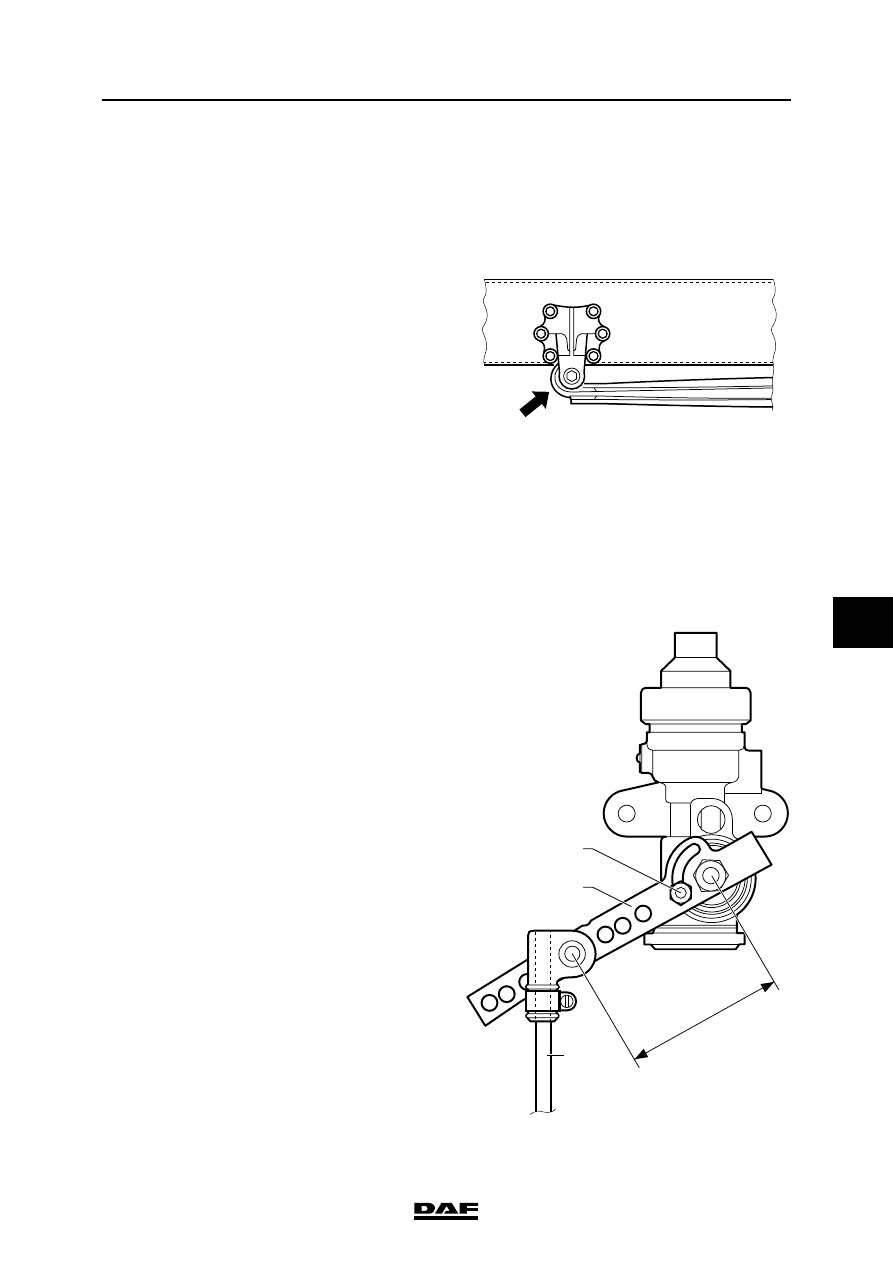
2.1 INSPECTION AND ADJUSTMENT, HEIGHT-CONTROL VALVE
1.
Measure the joint axle load of the leading
rear axle and the driven rear axle.
2.
Check the DAF number of the rear axle leaf
spring. The number is indicated on the front
of the leaf spring.
3.
Look up the axle load ratio of the vehicle
concerned. The axle load ratio is indicated
on the vehicle identification plate, fitted on
the left-hand side door post.
4.
Check the adjustment of the pressure-
limiting valve and adjust it if necessary.
5.
Check whether the bolt (A) is located in the
lower position of the slotted hole. Check
whether the bolt (A) is well tightened
6.
Measure the length l of the lever (B) and
check the lever length on the basis of the
value indicated in the table concerned, see
"Technical data". Adjust the lever length, if
necessary, to the length stated in the table.
7.
Fit a T-piece fitted with a test connection in
the pipe from the pressure-relief valve to the
air bellows.
8.
Connect a calibrated pressure gauge to the
test connection.
9.
Measure the bellows pressure. Look up in
the correct table, see "Technical data', the
relevant bellows pressure at the total axle
pressure measured and compare it with the
bellows pressure measured.
10. If the bellows pressure has to be adjusted,
the connection rod (C) between the lever and
the rear axle body must be extended or
shortened. Extending increases the pressure
and shortening decreases the pressure.
C9 00 436
A
B
C
l
W9 09 002