DAF CF65, CF75, CF85 Series . Manual - part 1067


  Index      DAF     DAF CF65, CF75, CF85 Series - service repair manual


Search            


Content   ..  1065  1066  1067  1068   ..


DAF CF65, CF75, CF85 Series . Manual - part 1067


©

 200424

4-1

Removal and installation

HYDRAULIC LIFTING GEAR

ΧΦ65/75/85 series

8

9

4. REMOVAL AND INSTALLATION

4.1 REMOVAL AND INSTALLATION, PUMP UNIT

Before removing components, the 

component concerned and the pipe 

connections should be cleaned. 

Working conditions should be very 

clean as even the smallest impurity 

can cause faults.

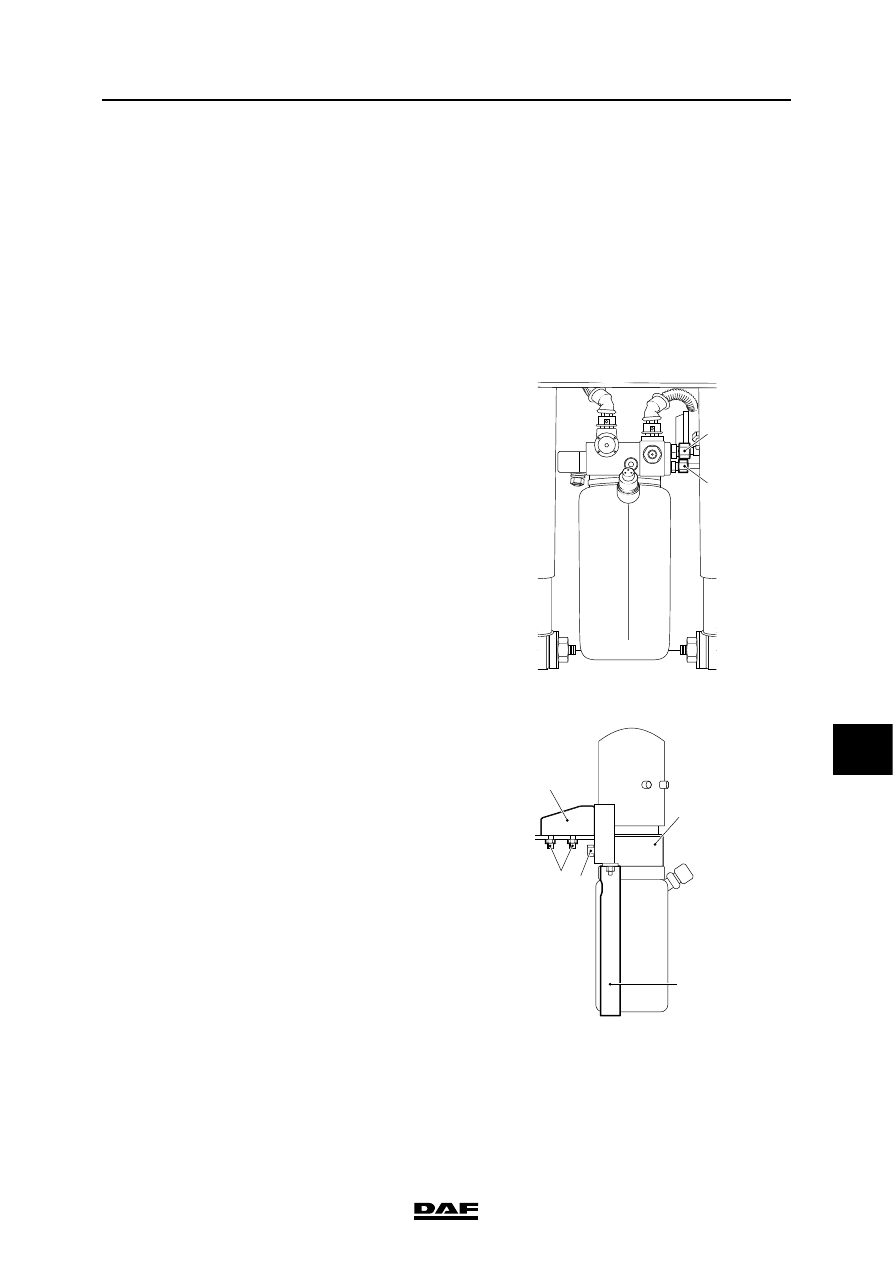
Removing the pump unit
1.

The wheels of the trailing axle must rest on 

the ground.

2.

Remove the fuse from the lifting gear.

3.

Mark the engine-wiring connection points 

and disconnect these.

4.

Mark the solenoid valve connectors and 

disconnect these.

5.

Remove the hydraulic lines from the pump 

unit.

Note: the pipe attached to pipe connection A 

may retain a residual pressure.

Wait for approx. 5 minutes after the trailing 

axle has been lowered before disconnecting 

the hydraulic lines from the pump unit. 

Collect the oil coming from the pipe. 

Plug the openings.

6.

Remove the bolts (5). Remove the 

support (1) and the attached pump unit (2).

7.

Remove the bracket (3).

8.

Remove the two attachment bolts (4) and lift 

the pump unit from the support (1).

9.

If a new pump unit is to be installed, the 

position of line connections (A) and (B) 

should be marked.

}


B

A

A8 00 281

1

2

3

4

5

A8 00 287

HYDRAULIC LIFTING GEAR

4-2

©

 200424

Removal and installation

9

ΧΦ65/75/85 series

8

Installing the pump unit
1.

If a new pump unit is to be installed, the line 

connections should be transferred. Make 

sure that the line connections are connected 

to the correct pump outputs.

-

The line connection which is equipped 

with M16 x 1.5 screw thread should be 

fitted to output A.

-

The line connection which is equipped 

with M18 x 1.5 screw thread should be 

fitted to output B.

2.

Fit the pump unit on its support.

3.

Fit the bracket around the reservoir.

4.

Fit the support on its chassis cross member.

5.

Fit the pipes.

6.

Reconnect the wiring and put the fuse back 

in.

7.

Fill the reservoir. See "Draining and filling".

8.

Inspect the line connections for leaks.

9.

Check the system pressure and the pressure 

relief valve. See "Inspection and 

adjustment".


B

A

A8 00 281

©

 200424

4-3

Removal and installation

HYDRAULIC LIFTING GEAR

ΧΦ65/75/85 series

8

9

4.2 REMOVAL AND INSTALLATION, 4/2 SOLENOID VALVE

Removing the 4/2 solenoid valve
1.

Remove the connector.

2.

Clean the valve and the surrounding area.

Work cleanly.

3.

Remove the nut (1) at the valve top and take 

the coil (4) from the valve.

4.

Remove the valve (6) from the valve block.

5.

The valve (6) itself cannot be disassembled.

Installing the 4/2 solenoid valve
1.

Renew the O-rings and the sealing ring.

2.

Apply a little oil to the valve (6) and install it 

into the valve block. Tighten the valve to the 

specified torque. See "Technical data".

3.

Check the O-rings (3) and (5) on the top and 

bottom of the coil (4) and fit it.

4.

Turn the coil (4) into the desired position and 

fit the spacer ring (2) with the nut (1).

5.

Fit the connector.

1
2
3

5

6

7
8
9

10

4

A8 00 252

HYDRAULIC LIFTING GEAR

4-4

©

 200424

Removal and installation

9

ΧΦ65/75/85 series

8

4.3 CHECKING THE FLUID LEVEL IN THE HYDRAULIC LIFTING GEAR

1.

Make sure that the trailing axle wheels are 

fully lowered and on the ground.

2.

Check the fluid level. The liquid level must be 

between the "min." and "max." level mark. If 

necessary, top up.


Content   ..  1065  1066  1067  1068   ..