DAF XF105. Manual - part 102
 

  Index      DAF     DAF XF105 - service repair manual


Search            


Content   ..  100  101  102  103   ..


DAF XF105. Manual - part 102


1

©

 200528

3-27

Control functions

DMCI ENGINE MANAGEMENT SYSTEM

XF105 series

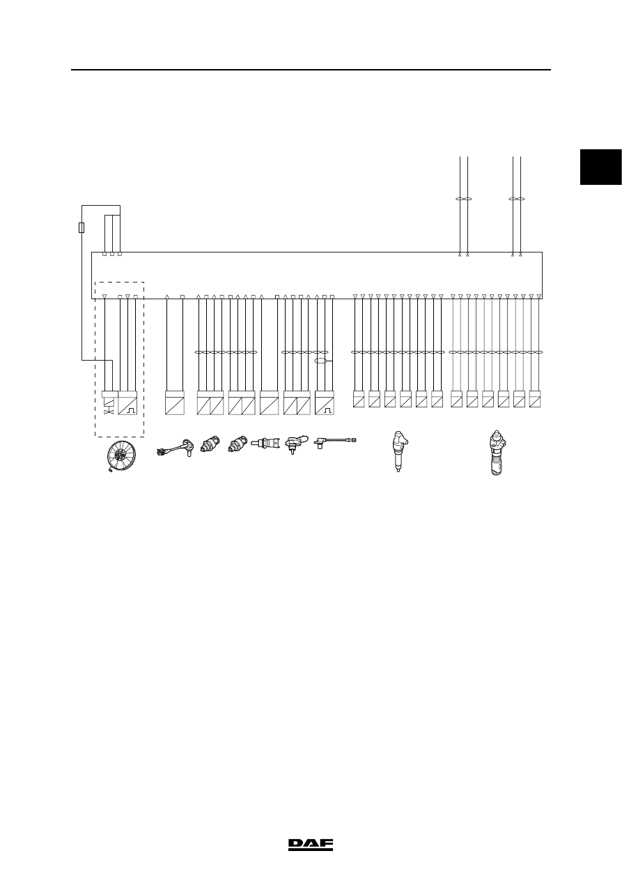
3.13 ENGINE PROTECTION FUNCTIONS

The general task of this function is to limit the 

requested quantity of fuel, related to the engine 

speed, atmospheric pressure, coolant 

temperature and other engine/vehicle conditions. 

The controls ensure that the engine and drive 

train are not mechanically and/or thermally 

overloaded. The engine torque is limited or 

reduced for this purpose. The protection 

functions can be sub-divided into two groups:

-

Thermal engine protection

-

Mechanical engine protection

Thermal engine protection
1.

Cooling problem detection

2.

Over-heating protection

3.

Exhaust gas temperature limitation

Mechanical engine protection:
1.

Turbocharger protection

2.

Height correction

3.

PTO/engine speed control torque limiting

4.

Fuel temperature correction

5.

Engine oil pressure protection

6.

Engine speed protection when engine is cold

7.

Excess engine speed detection

i401009

D965

1 2

high-side

low-side

Cyl.6

B136

1 2

high-side

low-side

Cyl.5

B135

1 2

high-side

low-side

Cyl.4

B134

1 2

high-side

low-side

Cyl.3

B133

1 2

high-side

low-side

Cyl.2

B132

A3

A7

A12

A23

A24

A15

A8

A19

A16

A4

A11

A20

1 2

high-side

low-side

Cyl.1

Pump units

B131

1 2

high-side

low-side

Cyl.6

B426

1 2

high-side

low-side

Cyl.5

B425

1 2

high-side

low-side

Cyl.4

B424

1 2

high-side

low-side

Cyl.3

B423

1 2

high-side

low-side

Cyl.2

B422

1 2

high-side

low-side

Cyl.1

Injectors

B421

4

pres.

F744

P

U

T

R

2 1

signal

3

signal

signal

ground

ground

oil

temp.

oil

temp.

F649

T

R

P

U

2 1

signal

ground

3 4

supply  5V

supply  5V

supply  5V

signal

shield

inlet

pres.

boost

4

pres.

F713

P

U

T

R

1 2

signal

3

signal

ground

fuel

temp.

fuel

N

5 1

supply  5V

signal

2

speed

fan

ground

T

R

1

signal

2

F566

F743

temp.

coolant

coolant

temp.

second

T

R

1

2

B335

oct.

fan

4

3

ground

signal

C16

C31

C36

C35

supply

supply

supply

C60

C61

C62

Vehicle

CAN2

low

Vehicle
CAN2
high

F

N

2 1

signal

return

3

F552

speed

crankshaft

A2

A8

A9

A22

A21

A14

A5

A18

A13

A1

A10

A17

C26

A34

A46

C25

A45

A41

C34

A42

C30

C29

C33

A38

A37

A27

A28

A30

A49

A50

A60

CAN2 low

CAN2 high

B53

B45

Vehicle

CAN1

low

Vehicle
CAN1
high

CAN1 low

CAN1 high

B35

B27

1

DMCI ENGINE MANAGEMENT SYSTEM

3-28

©

 200528

Control functions

XF105 series

Thermal engine protection
1. Cooling problem detection
The aim is to prevent over-heating due, for 

example, to a non-functioning coolant pump 

because of a broken poly-V-belt or a blockage or 

leak somewhere in the cooling system. This 

detection is active when the engine has been 

running for a certain time, the engine speed is 

higher than a certain value and the measured 

temperature from both temperature sensors 

(F566 and F743) is higher than a certain value.

There are three ways in which a cooling problem 

can be detected:

-

When the temperature difference between 

the two temperature sensors (F566 and 

F743) is higher than a certain value (F566 is 

located at cylinder 1 and F743 is located at 

cylinder 6). Too great a difference in 

temperature between cylinders 1 and 6 could 

mean that the coolant pump is not 

functioning properly.

-

When the signal from the second coolant 

temperature sensor (F743) rises too much 

within a certain time. A rapid rise on coolant 

temperature at cylinder 6 could mean that 

the coolant pump is not functioning correctly.

-

When no engine speed signal is received 

from the electronically-controlled fan clutch 

(B335). This could mean that the Poly-V belt 

is broken and that therefore the coolant 

pump is no longer operating.

If DMCI has recognised the cooling problem then 

the injected fuel will be limited so that the engine 

will be able to supply less torque. The yellow 

engine warning will also be activated.

Relevant components

-

Coolant temperature sensor (F566)

-

Second coolant temperature sensor (F743)

-

Electronically-controlled fan clutch (B335)

-

Crankshaft sensor (F552)

-

Pump units (B131 to B136)

-

Injectors (B421 to B426)

2. Over-heating protection
If the coolant temperature (F566) exceeds a 

specific maximum value, the maximum quantity 

of fuel to be injected is reduced. Heat 

development will be less as less energy is put into 

the engine.

Relevant components

-

Coolant temperature sensor (F566)

-

Pump units (B131 to B136)

-

Injectors (B421 to B426)

1

©

 200528

3-29

Control functions

DMCI ENGINE MANAGEMENT SYSTEM

XF105 series

3. Exhaust gas temperature limitation
The objective is to limit the exhaust gas 

temperature by limiting the maximum quantity of 

fuel to be injected and therefore to protect the 

turbine of the turbo against over-heating. This 

limit is a calculation of the exhaust manifold 

temperature, the maximum permissible exhaust 

gas temperature and the air flow trough the 

engine. This function is active above a certain 

engine speed and account is taken of the 

warming up of the turbo housing.

Relevant components

-

Charge boost pressure and temperature 

sensor (F649)

-

Crankshaft sensor (F552)

Mechanical engine protection
1. Turbocharger protection
a.
 Protection against too high a boost pressure

To protect the turbocharger against overrevving 

and to protect the engine against excessive 

mechanical loads, the torque is reduced if the 

boost pressure of the engine becomes (much) 

too high. The electronic unit uses engine speed 

(F552) and charge boost pressure (F649) signals 

to calculate whether the compressor speed and/

or the engine load is likely to become too high. 

Too high a speed of the turbocharger at a specific 

engine speed (for instance when the waste gate 

of the turbocharger is not functioning) may cause 

an excessive boost pressure. If the turbocharger 

speed becomes too high, the compressor wheel 

will deform too much and lubrication of the shaft 

will be inadequate; this may cause damage. To 

prevent this, less fuel is injected at this point and 

consequently the exhaust gas flow is reduced. 

The turbocharger speed will automatically 

become lower.

Relevant components

-

Crankshaft sensor (F552)

-

Charge boost pressure and temperature 

sensor (F649)

-

Pump units (B131 to B136)

-

Injectors (B421 to B426)

1

DMCI ENGINE MANAGEMENT SYSTEM

3-30

©

 200528

Control functions

XF105 series

b. Protection against too high a temperature

To protect the turbocharger against excessive 

exhaust gas temperatures, the injected quantity 

of fuel is reduced when the temperature of the 

exhaust gas becomes too high. The exhaust gas 

temperature is calculated by the electronic unit; it 

is not measured by a sensor. The electronic unit 

uses the engine speed (F552), charge boost 

pressure and charge temperature (F649) to make 

this calculation.

Relevant components

-

Crankshaft sensor (F552)

-

Charge boost pressure and temperature 

sensor (F649)

-

Pump units (B131 to B136)

-

Injectors (B421 to B426)

2. Height correction
Depending on the height (low atmospheric 

pressure), a maximum quantity of fuel to be 

injected is calculated. A decrease in the "quantity 

of air supplied" by the turbocharger as the vehicle 

is driven at a specific height may result in high 

exhaust gas temperatures. If the air is thinner, the 

quantity of fuel to be injected is adjusted, i.e. 

reduced, accordingly. 

Relevant components

-

Crankshaft sensor (F552)

-

Internal atmospheric pressure sensor

-

Pump units (B131 to B136)

-

Injectors (B421 to B426)

3. PTO/engine speed control torque limiting
During the various engine speed control functions 

via the steering column switch and the application 

connector ("nvar", "n2", "n3"), the quantity of 

injected fuel can limited to protect against 

overload of any PTO-driven components. This is 

a torque limiting function where the limiting 

percentage can be programmed with the aid of 

DAVIE XD. See also the control function "Engine 

speed control" and the document "Test and 

customer parameter information DAVIE XD".

Relevant components

-

Crankshaft sensor (F552)

-

PTO torque limiting active (software - 

customer parameters)

-

Pump units (B131 to B136)

-

Injectors (B421 to B426)


Content   ..  100  101  102  103   ..