DAF XF105. Manual - part 100


  Index      DAF     DAF XF105 - service repair manual


Search            


Content   ..  98  99  100  101   ..


DAF XF105. Manual - part 100


1

©

 200528

3-19

Control functions

DMCI ENGINE MANAGEMENT SYSTEM

XF105 series

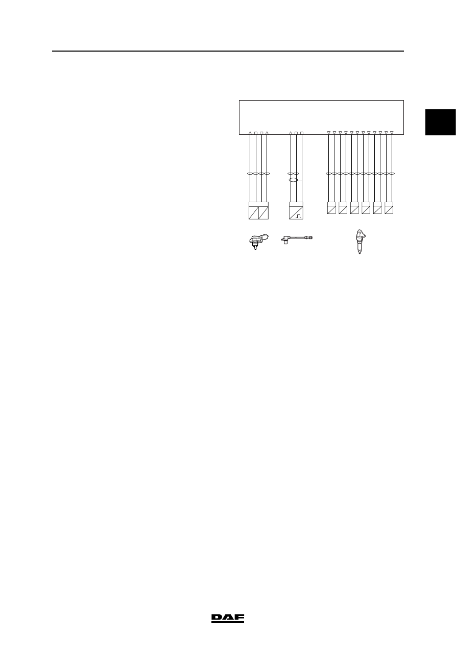
3.10 SMOKE LIMITATION

This function ensures that emissions of black 

smoke are kept to a minimum level. The fuel-air 

ratio is responsible for the development of 

smoke. The DMCI electronic unit calculates 

smoke limiting on the basis of the inlet air 

pressure (F649, pin A34) that is compensated by 

the inlet air temperature (F649, pin A30). To 

calculate the mass of the intake air, the electronic 

unit requires the inlet air temperature, the inlet air 

pressure and the intake air volume. The latter can 

be calculated on the basis of the cubic capacity 

and the speed of the engine. When the intake air 

mass has been calculated, the electronic unit can 

determine the maximum amount of fuel that can 

be injected to prevent excessive development of 

smoke.

If the inlet air boost pressure signal is absent or is 

not correct, the electronic unit carries out 

calculations using an air mass table based on the 

engine speed (F552).

Relevant components

-

Charge boost pressure and temperature 

sensor (F649)

-

Crankshaft sensor (F552)

-

Injectors (B421 to B426)

i401000

D965

1 2

high-side

low-side

Cyl.6

B426

1 2

high-side

low-side

Cyl.5

B425

1 2

high-side

low-side

Cyl.4

B424

1 2

high-side

low-side

Cyl.3

B423

1 2

high-side

low-side

Cyl.2

B422

1 2

high-side

low-side

Cyl.1

Injectors

B421

temp.

F649

T

R

P

U

2 1

signal

ground

3 4

supply  5V

signal

inlet

pres.

boost

N

2 1

signal

return

shield

3

F552

speed

crankshaft

A2

A8

A9

A22

A21

A14

A5

A18

A13

A1

A10

A17

A34

A27

A28

A30

A49

A50

A60

1

DMCI ENGINE MANAGEMENT SYSTEM

3-20

©

 200528

Control functions

XF105 series

3.11 ENGINE BRAKE CONTROL

The engine brake consists of an exhaust brake 

and, if fitted, a DEB (DAF Engine Brake). The 

engine brake can be activated by the driver 

(direct activation) or by another vehicle system 

(indirect activation).

Direct activation

The vehicle can be equipped with two engine 

brake switches, a standard floor switch (E564) 

and a steering column switch (C907) if the vehicle 

is not equipped with an intarder. Both switches 

are linked to VIC-2 (D310). VIC-2 sends a CAN 

message to DMCI to activate the engine brake. 

When the CAN message is received from VIC-2 

the exhaust brake valve (B192) and, if fitted, the 

DEB valves (B411 to B416) are actuated. 

However, the DCMI also takes into account other 

vehicle conditions (e.g. engine speed, vehicle 

speed and activation of ABS). When the engine 

brake is active, no fuel is injected until the 

engine speed drops to just above idling speed 

i400995

D965

1 2

high-side

low-side

Cyl.6

B416

1 2

high-side

low-side

Cyl.5

B415

1 2

high-side

low-side

Cyl.4

B414

1 2

high-side

low-side

Cyl.3

B413

1 2

high-side

low-side

Cyl.2

B412

1 2

high-side

low-side

DEB valves

Cyl.1

B411

shield

B192

valve

exh. brake

2

signal

1

supply

supply

supply

C60

C61

C62

Accelerator

Pedal  Sensor

Vehicle

CAN2

low

Vehicle
CAN2
high

E184
(10A)

N

2 1

signal

return

3

F552

speed

crankshaft

A38

C28

A49

A50

A60

A44

A43

A56

A55

A40

A39

A48

A47

A35

A52

A51

ground

signal

supply 5V

ground

signal

CAN2 low

CAN2 high

B A

C D F

F672

B37

B33

B34

B38

B41

B53

B45

Vehicle

CAN1

low

Vehicle
CAN1
high

CAN1 low

CAN1 high

B35

B27

H

B40

B40

ground

gearbox

E599

switch
neutral pos.

E593

switch
neutral pos.

B

C

ground

gearbox

kl.15

cabin

ground

E013
(10A)

E

B36

E575

2

1

+

HALL

-

6

clutch

switch

1

©

 200528

3-21

Control functions

DMCI ENGINE MANAGEMENT SYSTEM

XF105 series

(approx. 800 rpm). The engine brake is then 

disengaged and fuel is injected again after a 

small delay. The DEB valves (B411 to B416) are 

simultaneously and continuously actuated during 

activation of the engine brake.

AS Tronic receives a CAN message via V-CAN1 

if the engine speed is not optimal for engine brake 

use. If the speed is too low, AS Tronic will change 

down until the engine speed falls within the 

engine speed range for which the engine-brake 

capacity is optimal.

Activation via the floor switch (E564)
If the floor switch is pressed then VIC-2 sends a 

CAN message via V-CAN2 to DMCI to operate 

the engine brake.

The engine brake can only be engaged if the 

conditions below are satisfied:

1.

The engine speed must be higher than a 

programmed value and

2.

the vehicle speed must be higher than a 

programmed value and

3.

the ABS control must not be active.

4.

clutch pedal switch not active

5.

neutral position switch not operated

6.

idling switch may not be operated

1

DMCI ENGINE MANAGEMENT SYSTEM

3-22

©

 200528

Control functions

XF105 series

Activation via steering column switch (C907)
If the floor switch is not activated then the engine 

brake can be activated by briefly moving the 

steering column switch to the "ON" position (2). 

The steering column switch is a spring-loaded 

switch in this direction and returns after operation 

to the centre position. 

Activating the engine brake using the steering 

column switch is only possible if the following 

requirements are met:

-

Idling switch not active (accelerator pedal not 

operated)

-

Cruise control switch "SET-", "SET+" and 

"RES" not active

The engine brake activation using the steering 

column switch is deactivated if one of the 

following requirements is met:

1.

Steering column switch is in the "OFF" 

position (1)

2.

Idling switch is active (accelerator pedal 

operated)

3.

Cruise control switch "SET-", "SET+" and 

"RES" active

4.

Clutch pedal depressed

5.

Neutral position switch operated

Note:

The engine brake is deactivated during the 

activation of the clutch switch and/or the 

neutral position indicator (therefore not if the 

drive line is interrupted). If these switches 

are no longer active then the engine brake 

will be reactivated.

Indirect activation
The engine brake can also be activated at the 

request of another system such as the intarder 

(EST-42) and EBS-2.

- EBS-2

If EBS-2 sends the CAN message "EBS brake 

switch" via V-CAN2 to DMCI then DMCI will 

support vehicle braking by activating the engine 

brake.

This is the "third brake integration" function. This 

protects the brake lining during normal braking. 

This "third brake integration" function can also be 

deactivated using a dashboard switch.

i401010

1

3

5

6

7

2

4

i401011

1

2


Content   ..  98  99  100  101   ..