DAF 95XF. Manual - part 800


  Index      DAF     DAF 95XF Series - service repair manual


Search            


Content   ..  798  799  800  801   ..


DAF 95XF. Manual - part 800


1

INTERNAL CAB COMPONENTS

Inspection and adjustment

3-4

7

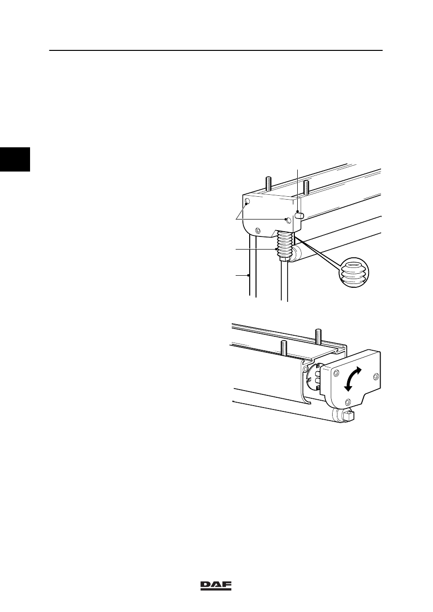
Adjusting roller sun blind, model II

Notes:
-

The spring tension of the roll-up mechanism
must be adjusted on the other side than the
side where the operating lever is located.

-

The attachment screws (4) of the side
cover may either be cross head screws or
torx screws.

1.

Loosen the socket head screw (1) until the
guide bracket (2) with end stop (3) can be
taken out of the side cover.

Note:
Make sure that the side cover is pressed
against the roller sun blind when removing
the attachment screws. If the side cover is
taken too far from the roller sun blind, the
internal spring of the roll-up mechanism will
fully expand.

2.

Remove the attachment screws (4) from
the side cover (if these are cross head
screws, remove them e.g. with a bent
screw driver).

K1 01 452

4

2

3

1

3.

Take the side cover so far from the roller
sun blind that the side cover is able to turn.
Adjust the spring tension of the roll-up
mechanism.

4.

Press the side cover fully against the roller
sun blind and fit the attachment screws (4).

5.

Fit the guide bracket (2) with end stop (3) in
the side cover. Tighten the socket head
screw (1). Press the end stop (3) in the side
cover.

6.

Check that the roll-up mechanism is
working properly.

K1 01 453

2

ᓻ 0209

1

Removal and installation

INTERNAL CAB COMPONENTS

4-1

4. REMOVAL AND INSTALLATION

4.1 REMOVAL AND INSTALLATION, SWITCHES

Removing switches
1.

Insert a feeler gauge of approx. 1 mm
straight between the switch and the panel at
the side of the finger-sized depression (A),
until it touches the inside of the panel.

2.

Remove the switch from its locked position
by carefully moving the feeler gauge in the
direction of the arrow (B).

3.

Carefully remove the switch from the panel.
In doing so, ensure that the connector lock
does not catch behind the panel, causing
the connector to fall behind the panel.

4.

If necessary, remove the switch from the
connector.

A

B

K1 01 334

Installing switches
1.

Fit the connector.

2.

Insert the switch into the opening in the
panel and press until you can feel it lock.

A

B

K1 01 335

2

ᓻ 0209

1

INTERNAL CAB COMPONENTS

Removal and installation

4-2

4.2 REMOVAL AND INSTALLATION, INSTRUMENT PANEL

Removing instrument panel
1.

Remove the cover above the instrument
panel.

K100427

2.

Remove the attachment bolts at the top of
the instrument panel.

K100428

3.

Remove the two outer switches at the
bottom of the instrument panel.

4.

Remove the attachment bolts beneath the
switches, after which you can pull the panel
forward. If the panel is to be removed, mark
the electrical and pneumatic connections
first.

Installing instrument panel
1.

Connect up all the electrical and pneumatic
connections of the instrument panel.

2.

Fit the panel. Be careful not to jam any
wires between the panel and the frame.

3.

Re-fit the switches.

4.

Fit the cover above the instrument panel.

K100429

2

ᓻ 0209

1

Removal and installation

INTERNAL CAB COMPONENTS

4-3

4.3 REMOVAL AND INSTALLATION, RADIO PANEL

Removing radio panel
1.

Remove the attachment screws.

2.

Slide the radio panel out of the instrument
panel.

3.

If necessary, mark the location of the
connectors and remove them from the
switches.

4.

Remove the panel.

Installing radio panel
1.

Fit the connectors.

2.

Slide the radio panel behind the instrument
panel.

3.

Fit the attachment screws.

K100430

4.4 REMOVAL AND INSTALLATION, LOWER CENTRAL CONSOLE STORAGE

COMPARTMENT

Removing lower central console storage
compartment
1.

Remove the rubber inlay and the
attachment screws from the lower storage
compartment.

2.

Remove the electrical wiring harness from
the cigarette lighter and the accessories
port, after which you may remove the
storage compartment.

Installing lower central console storage
compartment
1.

Fit the lower storage compartment. Make
sure that the electrical wiring is underneath
the storage compartment.

2.

Tighten the attachment screws and put the
rubber inlay in the storage compartment.

K100332

2

ᓻ 0209


Content   ..  798  799  800  801   ..