DAF 95XF. Manual - part 127
6
Description of components
DESCRIPTION OF BRAKE COMPONENTS
1-45
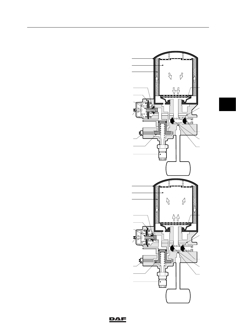
1.20 AIR DRYER
Purpose
The purpose of the air dryer is to remove water,
oil and other foreign matter from the air before it
enters the brake system, and to adjust the
system pressure by means of a built-in pressure
regulator.
BOSCH design
Operation
Filling the system
The air supplied by the compressor reaches the
air dryer via port (1) and passes the
venting/safety valve (9).
The air flows to filter element (1) via a bore.
In the filter element, the air passes through
coarse filter (3), which sieves out the oil and dirt
particles.
In addition, the air condenses against the cool
wall of the element. Next, the air passes through
the dessiccant.
The special filter dessiccant grains have a very
high absorbing capacity, which means that the
grains extract water vapour from the air. Dust
filter (15) prevents grains or dust from becoming
airbound.
The air thus dried flows via non-return valve (13)
to exhaust port (21).
At the same time a small part of the dried air
flows through constriction (12) to exhaust (22).
A small reservoir, the regeneration reservoir, is
connected to exhaust (22).
If the filter element should become clogged and
thus cause a pressure increase, over-flow valve
(11) will open and connect input (1) and
exhaust (21).
1
3
21
22
23
1
23
1
2
3
6
7
8
9
10
12
11
13
14
15
5
4
3
21
22
1
2
3
6
7
8
9
10
12
11
13
14
15
5
4
R600242
3
ǹ 0006