Citroen C3 Pluriel (2008 year). Instruction - part 8


  Index      Citroen     Citroen C3 Pluriel - instruction 2008 year in english


Search            


Content   ..  6  7  8  9   ..


Citroen C3 Pluriel (2008 year). Instruction - part 8


A

B

V

115 

1 2 V   B AT T E R Y

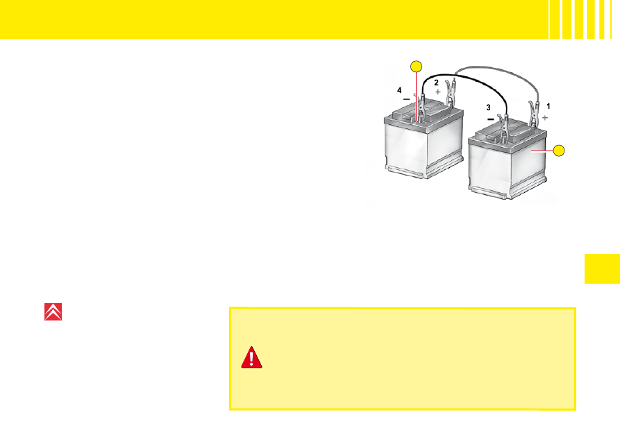
Starting the engine with an assisting battery

If the battery is discharged, it is possible to use either a separate 
emergency battery or a battery on another vehicle.
A. Dischargedbattery (Under the bonnet)
B. Assisting battery
Check that the assisting battery has suffi cient voltage (12 V).
If  you  use  the  battery  on  another  vehicle,  stop  the  engine  on  the 
latter. The two vehicles must not come into direct contact with each 
other.
Connect the cables according to the order indicated in the diagram. 

order

Check that the leads are well secured (risk of sparks).
Start  the  engine  of  the  assisting  vehicle.  Let  the  engine  run  for 
around 1 minute at a slightly accelerated idle.
Operate the starter on the vehicle being assisted.
Note:  For any operation necessitating a disconnection of the bat-
tery, you must wait 3 minutes after switching the ignition off, taking 
no  action  which  will  prevent  the  vehicle's  electrical  system  from  going  to  sleep  (such  as  operating  the  doors  and 
tailgate, pressing the buttons on the remote control, etc.).

Never approach with a fl ame or create sparks in the vicinity 

of the battery (explosive gas).
The  battery  contains  dilute  sulphuric  acid  which  is  highly 
corrosive.
When  handling  batteries,  always  protect  your  face  and 
especially your eyes.
In the event of any contact with the skin, rinse immediately 
with copious amounts of fresh water.

Advice

Do not touch the leads during 
the operation.

Do not lean over the batteries.
Disconnect  the  cables  in  reverse 
order,  making  sure  they  do  not 
touch together.

VI

116 

R E F U E L L I N G

To open the fl ap, pull at the edge.

Locking fi ller cap

Turn the key a quarter turn to lock 

and unlock the fi ller cap.
When  refuelling,  place  the  cap  in 
the support provided on the inside 

of the fi ller fl ap.
For  a  petrol  engine  with  a  cata-
lytic  converter,  unleaded  fuel  is 
compulsory.
The  fi ller  neck  is  narrower  to 

ensure that only unleaded petrol 
can be put in.

When you are seeking to fi ll your tank, do not persist after the third 

cut-off ; that could cause your vehicle to malfunction.

Fuel tank capacity (in litres):

 Approx. 47.

If you should put in fuel that is not suitable for your vehicle's 
engine type, it is imperative to have the tank drained before 
you start the engine again.

FUEL QUALITY

A label inside the fi ller fl ap tells you which type of fuel to use.

UNLEADED PETROL

DIESEL FUEL

The petrol engines are designed to run on RON 95.
However, for better performance (petrol engine), we recommend RON 98.

1

3

2

4

VI

117 

C H A N G I N G   B U L B S

HEADLAMP UNIT

1. Dipped beams
2. Main beams
3. Sidelamps
4. The direction indicator warn-

ing lamps

Note:  A  light  misting  may  appear 
on the headlamp surface in certain 
conditions of use.

Note:  To  change  the  bulbs  in  the 
LH headlamp lens:

Remove the battery cover.
Detach the fusebox cover.


Main beams

Tilt  the  metallic  spring  holding  the 

fl ap  giving  access  to  the  lamp 

bulbs.
Open the access fl ap.
Disconnect the connector.
Disengage the retaining spring.
Take out the bulb.
Bulb: H1

Dipped beams

Tilt  the  metallic  spring  holding  the 

fl ap  giving  access  to  the  lamp 

bulbs.
Open the access fl ap.
Disconnect the connector.
Disengage the retaining spring.
Take out the bulb.
Bulb: H7

Front foglamps

Bulb: H1

VI

118 

C H A N G I N G   B U L B S

Front direction indicator

Rotate  the  bulb-  holder  a  quarter 
turn and pull.
Release the bulb.
Bulb: PY 21 W (amber).

Sidelamps

Tilt  the  metallic  spring  holding  the 

fl ap  giving  access  to  the  lamp 

bulbs.
Open the access fl ap.
Rotate  the  bulb-  holder  a  quarter 
turn and pull.
Bulb: W 5 W

Side  repeater  direction  indi-
cator

To  change  the  direction  indicator 
side  repeater,  push  it  forwards  or 
rearwards  to  detach  it,  then  pull  it 
towards you.
Hold the cable and disconnect it.
Contact a CITROËN dealer.

VI

119 

C H A N G I N G   B U L B S

Interior lamp

Unclip the transparent cover of the 
interior lamp to reach the bulb.
Bulb: W 5 W

Spotlamps

Unclip the transparent cover of the 
interior lamp to reach the bulb.
Bulb: W 5 W

Boot lamp

Unclip the transparent cover of the 
interior lamp to reach the bulb.
Bulb: W 5 W

3

1

2

VI

120 

C H A N G I N G   B U L B S

Rear lamp unit

Identify the failed bulb.
Bulbs: 

1. Stop-lamps and sidelamps: 

P 21 W/5 W.

2. Direction indicator: PY 21 W.
3. Foglamp: P 21 W.

Left hand side
Reversing lamp: P 21 W.
Right hand side

Removal

Remove  the  tailgate  balancing 
strut  by  removing  the  retaining 
clip.
Undo the lamp fi xing screws.
Remove  the  bulb-  holder  to 
access the bulb.


Refi t  the  assembly  after  replacing 

the bulb.

VI

121 

C H A N G I N G   B U L B S

Third stoplamp

Undo the fi xing screws to remove 

the tailgate interior trim.
Unclip  the  bulb-  holder  to 
access the bulbs.

Bulb: W 5 W.

Number plate

Unclip  the  lens  then  pull  the  bulb- 
holder.
Bulb: W 5 W.

After each operation, check that the lamps work.

A

VI

122 

S A F E T Y   R E C O M M E N D A T I O N S

Towbar

We recommend you to have this device fi tted by a CITROËN Dealer, who will be acquainted with your vehicle’s tow-

ing capability and with the procedures necessary for installing a safety item of this kind.

Dimensions (in metres)

A

: 0.738

Do not exceed the maximum permitted load.
For the maximum distributed load on the roof bars: see the 
chapter “General”.
To  avoid  damage,  do  not  remove  the  roof  arches  with  the 
roof bars attached. Make sure that the load on the roof is not 
hindering the sliding of the folding roof.

Roof bars

For your safety and to avoid damage to the roof, you should use roof bars that are tested and approved by AUTO-
MOBILES CITROËN for the design of your particular vehicle.

For your safety and to avoid damage to the roof, you should use 

safety and 

Recommendations:

Spread the load evenly, avoiding overloading on one side.
Position the heaviest weight as low down as possible.
Tie the load down securely and add warning signs if it is protruding.
Drive conservatively, as the vehicle will be more vulnerable to side winds.
The stability of your vehicle may be altered.
Remove  the  roof  rack  or  roof 
bars  when  you  are  not  using 
them.

Note:  It  is  possible  to  open  the 
sun  roof  even  when  the  roof  bars 
are present.


123 

C H A N G I N G   A   W H E E L

Access to the spare wheel

To access the spare wheel
Lift the boot carpet.
Remove the jack- holder to access the wheel.

Tools

The tools are to be found in a protective holder inside the spare wheel.
Note: 

In cabriolet or spider confi guration, it is necessary to move the roof 

cassette in order to access the spare wheel.

To reposition the spare wheel

Return the wheel to the boot, place the toolbox inside the wheel, then secure 
using the strap.

Tyre pressures

This is indicated on the label on the front door pillar. See “Vehicle identifi ca-

tion” and “User Precautions”.

Advice

The wheel bolts are specifi c to the type of wheel.

If the type of wheel is changed, check with your CITROËN dealer that the wheel bolts are compatible with the new 
wheels.

The jack and all the tools are designed specifi cally for use on 

your particular vehicle.
Do not use them for any other applications.
With a spare wheel, drive cautiously.

6

3

2

5

1

4

VI

124 

C H A N G I N G   A   W H E E L

Removal

1. 

Park the vehicle on stable, fi rm ground that is not slippery. Apply the 

parking brake.

Switch off the ignition and engage fi rst gear or reverse gear, depending 

on any slope.
You must ensure that all of the vehicle occupants have left the vehi-
cle and are in a safe location.

2. Detach the wheel trim if there is one, using the end of the wheelbrace 4

pulling close to the valve.

3. 

Slacken the wheel bolts. For vehicles with aluminium wheel rims, fi rst 

remove the bolt protectors using tool 6 and use the socket for the anti- 
theft bolt 5.

4. Position the jack 1 at the vehicle subframe jacking point closest to the 

wheel to be changed. Make sure that the whole surface of the jack 
base is in contact with the ground.

5. Expand the jack 1 until the wheel is a few centimetres above the 

ground.

6. Remove the uppermost bolt.
7. Undo the other bolts, remove the wheel.

Tools

1. 

Jack.

2. Movable towing eye.
3. Compartment for bulb kit (Not supplied).
4. Wheelbrace.
5. Socket for anti- theft bolts (For vehicles with aluminium wheel rims).
6. Tool for removing wheel bolt protectors (For vehicles with aluminium 

wheel rims).

VI

125 

C H A N G I N G   A   W H E E L

Refi tting

1. Engage the wheel on the hub.
2. Screw in the bolts but do not fully tighten them.
3. Lower the jack and remove it.
4. Tighten the wheel bolts, using the wheelbrace.
5. 

Refi t the embellisher, taking care to accommodate the tyre valve. For 

vehicles equipped with aluminium rims, refi t the wheel bolt protectors.

6. 

Have the original wheel repaired and refi tted as soon as possible.

7. 

Make sure that the tyre is at the correct pressure (see “Vehicle Iden-

tifi cation” and “User Precautions”) and have the wheel balancing 

checked.

Dimension of the spare wheel

If your spare wheel is of a dimension different to that of the wheels normally 

fi tted on your vehicle (identifi ed by a label), it is essential to use the spare 

wheel only on a temporary basis, to drive carefully, not to exceed 80 km/h 

(50 mph), to have the original wheel refi tted as soon as possible and never to drive with more than one spare wheel 

of a different dimension fi tted on your vehicle.

Never get underneath the vehicle if it is supported only by the jack.
When changing a wheel, it is essential to park the vehicle safely on level and stable ground.

Wheel for temporary use

If your vehicle has light alloy wheel rims but a steel spare wheel, if you fi t 

the latter it is normal to notice that the wheel bolts do not appear to contact 
on the rim.
The spare wheel is secured by the conical tapering of the wheel bolt’s shaft 
(See illustration).
when refi tting the light alloy wheel, make sure that the tapering contact faces 

of the wheel bolts are clean and in good condition.

126 

T O W I N G   –   L I F T I N G

Towing with wheels on the ground

Towing eye fi xings are located at the front and at the rear of the vehicle.
To access them:

Carefully lift the access cover.
Release it by pressing on the lower part.

A lug keeps the cover attached to the bumper, so that it does not become 
lost.
The ignition key must be in position M to retain steering.
Use a bar with attachments to the towing eyes as above.

Vehicles with manual gearbox (diesel engine)
For vehicles fi tted with a manual gearbox, the gear lever must be in neutral. 

If neutral is not engaged, certain brake components may be damaged and 
braking assistance may not function when re-starting the engine.


Movable towing eye

The towing ring is detachable and 

can be fi tted either at the front or at 

the rear of the vehicle. It is stowed 
in the jack's protective holder in the 
spare wheel.

When the engine is not running, the steering and the braking 
are no longer assisted.
If  you  are  towing  another  vehicle,  the  latter  must  be  free-
wheeling (gearbox in neutral).

Advice

Towing at low speed over a very 
short  distance
  is  authorised  in 
exceptional  cases  depending  on 
the regulations in force.
Otherwise,  it  is  necessary  to 
have  your  vehicle  transported 
on a recovery truck.

PRECAUTIONS  WHEN  TOW-
ING SENSODRIVE GEARBOX

Place the selector on position N 
(neutral).

VII

127 

G E N E R A L

MAV: Unladen weight.
MTAC: Gross vehicle weight.
CMAE  AR:  Maximum  weight  on 
rear axle.
MTRA: Gross train weight.
Weights: Refer to the manufactur-
er's plate.
BVM: Manual gearbox.
BVMP: Electronic Gearbox System.

Observe  your  vehicle's  towing 
limits.
It  is  essential  to  comply  with  the 
max.  Gross  Trailer  Weights  and 

speed limits as specifi ed by legis-

lation in each country. 
For  further  information  about  the 
towing  capacity  of  your  vehicle 
and  its  max.  authorised  Gross 
Train  Weight,  contact  a  CITROËN 
dealer.

Engine type

1.4i

BVM

1.6i 16V

BVMP

HDi 70

BVM

Fuel tank capacity

Approximately 47 litres

Fuels to be used

Unleaded petrol

 RON 95 - RON 98

Diesel 

fuel

Turning circle between walls (in metres)

11.55

11.55

11.55

French fi scal rating

5

7

4

Calculated maximum speed in km/h (mph) 
(In the highest gear)

160 (99) 182 (113)  158 (98)

Weights (kg)

Unladen weight (MAV)

1 136

1 177

1 189

Gross vehicle weight (MTAC)

1 506

1 543

1 536

Maximum weight on rear axle 
(CMAE AR)

735

735

735

Gross train weight (MTRA)

2 106

2 143

2 136

Gross trailer weight (with brakes) 
(Within the Gross Train Weight limit)

850

850

850

Gross trailer weight (without brakes)

540

600

540

Trailer nose weight

32

32

32

Maximum roof rack load

50

Dimensions of chainable tyres

185/65 R15

G

B

E

H

I

F

VII

128 

D I M E N S I O N S

( I N   M E T R E S )

A

2.460

B

3.934

C

0.779

D

0.695

E

1.431

F

1.430/1.435

G

1.700

H

1.559/1.563

I

1.877

E

A

D

C

G

F

B

H

VII

129 

D I M E N S I O N S

( I N   M E T R E S )

A

0.987

B

0.400

C

0.660

D

0.885

E

0.645

F

1.180

G

0.730

H

0.635

VII

130 

F U E L   C O N S U M P T I O N

( I N   L I T R E S / 1 0 0   K M   ( M I L E S   P E R   G A L L O N ) )

These consumption fi gures are established according to Directive 80/1268/CEE. Fuel consumption can vary depend-

ing on style of driving, traffi c conditions, weather conditions, vehicle load, how the vehicle has been maintained and 

on use of accessories.

Engine type

1.4i

1.6i 16 V

HDi 70

Saloon

BVM

BVMP

BVM

Urban

8.9 (31.7)

8.3 (34.0)

5.5 (51.4)

Extra urban

5.5 (51.4)

5.5 (51.4)

4.0 (70.6)

Combined

6.8 (41.5)

6.6 (42.8)

4.5 (62.8)

CO

2

 emissions

Combined (g/km)

163

157

120

The fuel consumption fi gures quoted are correct at time of going 

to press.

BVM: Manual gearbox.
BVMP: Electronic Gearbox System.


Content   ..  6  7  8  9   ..