Chrysler Town, Dodge Caravan. Manual - part 514
REMOVAL
The rear blower motor and blower wheel are ser-
viced only as a balanced unit. If either component is
faulty or damaged, the entire unit must be replaced.
WARNING: REFER TO THE APPLICABLE WARN-
INGS AND CAUTIONS FOR THIS SYSTEM BEFORE
PERFORMING
THE
FOLLOWING
OPERATION.
(Refer to 24 - HEATING & AIR CONDITIONING/
PLUMBING - FRONT - WARNING - A/C PLUMBING),
(Refer to 24 - HEATING & AIR CONDITIONING/
PLUMBING - FRONT - CAUTION - A/C PLUMBING),
and (Refer to 24 - HEATING & AIR CONDITIONING/
PLUMBING - FRONT - WARNING - HEATER PLUMB-
ING).
(1) Remove the rear heater-A/C unit housing from
the vehicle. (Refer to 24 - HEATING & AIR CONDI-
TIONING/DISTRIBUTION - REAR/REAR HEATER-
A/C HOUSING - REMOVAL).
(2) Disconnect the rear blower motor pigtail wire
connector. With manual temperature control, the
blower pigtail wire is connected to a take out and
connector of the rear HVAC wire harness. With auto-
matic temperature control, the blower pigtail wire is
connected to a receptacle on the blower power mod-
ule.
(3) Remove the three screws that secure the
blower motor to the outboard side of the rear heater-
A/C unit housing (Fig. 5).
(4) Remove the blower motor and blower wheel
from the rear heater-A/C unit housing.
INSTALLATION
(1) Position the blower motor and blower wheel
onto the outboard side of the rear heater-A/C unit
housing.
(2) Install and tighten the three screws that secure
the blower motor to the rear heater-A/C unit housing.
Tighten the screws to 2 N·m (18 in. lbs.).
(3) Reconnect the rear blower motor pigtail wire
connector. With manual temperature control, the
blower pigtail wire is connected to a take out and
connector of the rear HVAC wire harness. With auto-
matic temperature control, the blower pigtail wire is
connected to a receptacle on the blower power mod-
ule.
(4) Reinstall the rear heater-A/C unit housing into
the vehicle. (Refer to 24 - HEATING & AIR CONDI-
TIONING/DISTRIBUTION - REAR/REAR HEATER-
A/C HOUSING - INSTALLATION).
REAR HEATER-A/C HOUSING
REMOVAL
WARNING: REFER TO THE APPLICABLE WARN-
INGS AND CAUTIONS FOR THIS SYSTEM BEFORE
PERFORMING
THE
FOLLOWING
OPERATION.
(Refer to 24 - HEATING & AIR CONDITIONING/
PLUMBING - FRONT - WARNING - A/C PLUMBING),
(Refer to 24 - HEATING & AIR CONDITIONING/
PLUMBING - FRONT - CAUTION - A/C PLUMBING),
and (Refer to 24 - HEATING & AIR CONDITIONING/
PLUMBING - FRONT - WARNING - HEATER PLUMB-
ING).
(1) Recover the refrigerant from the refrigerant
system. (Refer to 24 - HEATING & AIR CONDI-
TIONING/PLUMBING - FRONT/REFRIGERANT -
STANDARD
PROCEDURE
-
REFRIGERANT
RECOVERY).
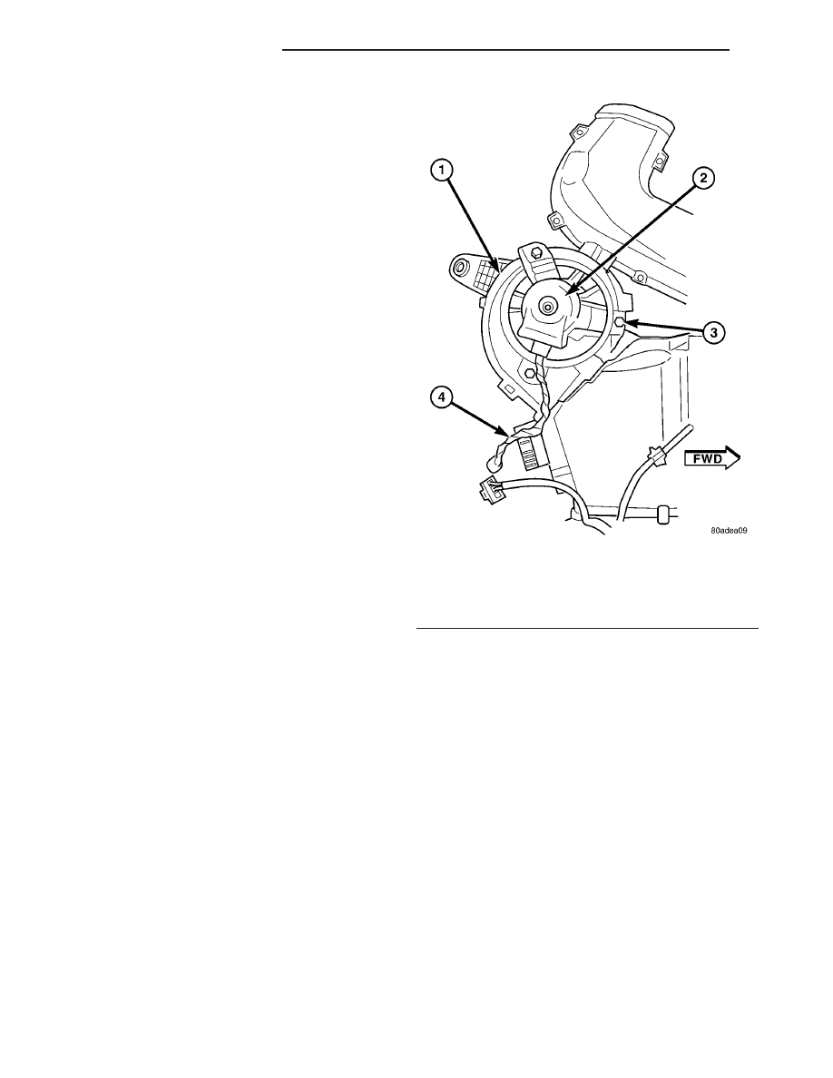
Fig. 5 Blower Motor
1 - REAR HEATER-A/C UNIT HOUSING
2 - BLOWER MOTOR
3 - SCREW (3)
4 - BLOWER PIGTAIL WIRE
24 - 56
DISTRIBUTION - REAR
RS
BLOWER MOTOR (Continued)