Chrysler Town, Dodge Caravan. Manual - part 442
(a) Open door to mid-point of travel.
(b) Mark outline of upper roller arm on door to
assist in making adjustments.
(c) Loosen bolts attaching upper roller arm to
door (Fig. 9).
(d) Decrease the length of the upper roller arm
to increase seal compression.
(e) Increase the length of the upper roller arm to
decrease seal compression.
(f) Tighten all upper roller arm bolts.
(g) Verify door alignment, adjust as necessary.
(3) Adjust seal compression at the bottom of B-post
seal.
(a) Open door to mid-point of travel.
(b) Mark outline of lower roller arm on lower
roller arm bracket to assist in making adjustments
(Fig. 15).
(c) Loosen bolts holding lower roller arm to
lower roller arm bracket.
(d) Pivot lower roller arm toward center of vehi-
cle to decrease seal compression.
(e) Pivot lower roller arm outward to increase
seal compression.
(f) Tighten lower roller arm bolts.
(g) Verify alignment, adjust as necessary.
NOTE: Adjusting seal compression at the B-post
can affect door flushness the C-post.
STABILIZER ADJUSTMENT - UPPER/LOWER
(1) Open sliding door.
(2) Loosen the bolts holding the male stabilizers to
the sliding door enough that the stabilizers can move
with some effort.
(3) Close and then reopen sliding door.
(4) Tighten all stabilizers bolts.
STABILIZER
REMOVAL
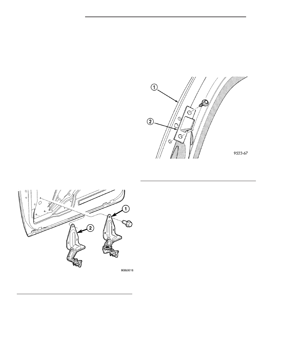
(1) Open sliding door.
(2) Remove screws attaching stabilizer to door end
frame (Fig. 16).
(3) Remove stabilizer from vehicle.
INSTALLATION
(1) Place stabilizer in position on vehicle.
NOTE: Loose install screws first. Fit should be
snug but free to move when closing door to align to
body half stabilizer.
(2) Install screws attaching stabilizer to door end
frame.
(3) Open door and final tighten screws.
(4) Verify sliding door operation.
STABILIZER SOCKET
REMOVAL
(1) Open sliding door.
(2) Remove screws holding stabilizer socket to
B-pillar (Fig. 17).
(3) Remove stabilizer socket from vehicle.
INSTALLATION
(1) Place stabilizer socket in position on vehicle.
(2) Install screws to hold stabilizer socket to B-pil-
lar. Tighten nuts to 5 N·m (45 in. lbs.) torque.
(3) Close sliding door and verify operation.
Fig. 15 Sliding Door Lower Roller Arm
1 - POWER LOWER ROLLER ARM
2 - MANUAL LOWER ROLLER ARM
Fig. 16 SLIDING DOOR STABILIZER
1 - SLIDING DOOR
2 - STABILIZER
23 - 32
DOORS - SLIDING
RS
SLIDING DOOR (Continued)