Chrysler Town, Dodge Caravan. Manual - part 429


  Index      Chrysler     Chrysler TOWN & COUNTRY, VOYAGER, Dodge Caravan - service repair manual 2001-2007 year


Search            


Content   ..  427  428  429  430   ..


Chrysler Town, Dodge Caravan. Manual - part 429


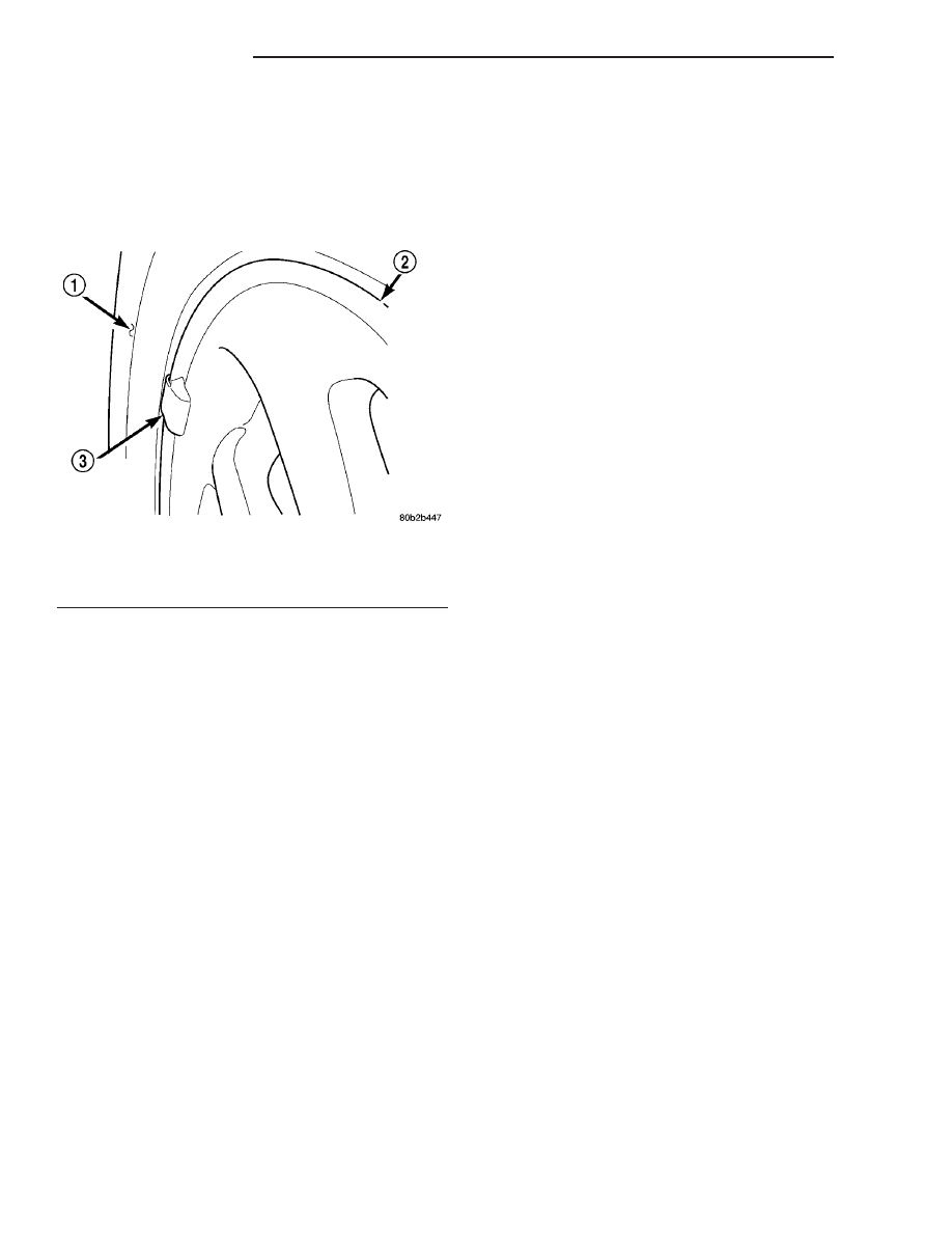
unique wheel weights. They are designed to fit the
contour of the wheel (Fig. 1).

• Inspect tires and wheels for damage, mud pack-

ing and unusual wear; correct as necessary.

• Check and adjust tire air pressure to the pres-

sure listed on the label attached to the rear face of
the driver’s door.

ROAD TEST

Road test vehicle on a smooth road for a least five

miles to warm tires (remove any flat spots). Lightly
place hands on steering wheel at the 10:00 and 2:00
positions while slowly sweeping up and down from 90
to 110 km/h (55 to 70 mph) where legal speed limits
allow.

Observe the steering wheel for:
• Visual Nibble (oscillation: clockwise/counter-

clockwise, usually due to tire imbalance)

• Visual Buzziness (high frequency, rapid vibra-

tion up and down)

To rule out vibrations due to brakes or powertrain:
• Lightly apply brakes at speed; if vibration occurs

or is enhanced, vibration is likely due to causes other
than tire and wheel assemblies.

• Shift transmission into neutral while vibration

is occurring; if vibration is eliminated, vibration is
likely due to causes other than tire and wheel assem-
blies.

For brake vibrations, (Refer to 5 - BRAKES -

BASE/HYDRAULIC/MECHANICAL/ROTORS

-

DIAGNOSIS AND TESTING).

For powertrain vibrations, (Refer to 3 - DIFFER-

ENTIAL & DRIVELINE - DIAGNOSIS AND TEST-
ING).

For tire and wheel assembly vibrations, continue

with this diagnosis and testing procedure.

TIRE AND WHEEL BALANCE

(1) Balance the tire and wheel assemblies as nec-

essary following the wheel balancer manufacturer’s
instructions and using the information listed in Stan-
dard Procedure - Tire And Wheel Balance. (Refer to
22 - TIRES/WHEELS - STANDARD PROCEDURE)

(2) Road test the vehicle for at least 5 miles, fol-

lowing the format described in Road Test.

(3) If the vibration persists, continue with this

diagnosis and testing procedure.

TIRE AND WHEEL RUNOUT/MATCH MOUNTING

(1) System Radial Runout. This on-the-vehicle

system check will measure the radial runout includ-
ing the hub, wheel and tire.

(a) Raise vehicle so tires clear floor. (Refer to

LUBRICATION & MAINTENANCE/HOISTING -
STANDARD PROCEDURE)

(b) Apply masking tape around the circumfer-

ence of the tire in the locations to be measured
(Fig. 2). Do not overlap the tape.

(c) Check system runout using Dial Indicator

Set, Special Tool C-3339A with 25-W wheel, or
equivalent. Place the end of the indicator against
each taped area (one at a time) (Fig. 2) and rotate
the tire and wheel. System radial runout should
not exceed 0.76 mm (0.030 inch) with no tread
“dips” or “steps.” Tread “dips” and “steps” can be
identified by spikes of the dial indicator gauge.
• Tread 9dips9; Rapid decrease then increase in

dial indicator reading over 101.6 mm (4.0 inch) of
tread circumference.

• Tread 9steps9; Rapid decrease or increase in dial

indicator reading over 101.6 mm (4.0 inch) of tread
circumference.

(d) If system runout is excessive, re-index the

tire and wheel assembly on the hub. Remove
assembly from vehicle and install it back on the
hub two studs over from original mounting posi-
tion. If re-indexing the tire and wheel assembly
corrects or reduces system runout, check hub
runout and repair as necessary (Refer to 5 -
BRAKES

-

BASE/HYDRAULIC/MECHANICAL/

ROTORS - DIAGNOSIS AND TESTING).

(e) If system runout is still excessive, continue

with this diagnosis and testing procedure.
(2) Tire and Wheel Assembly Radial Runout.

This radial runout check is performed with the tire
and wheel assembly off the vehicle.

(a) Remove tire and wheel assembly from vehicle

and install it on a suitable wheel balancer.

(b) Check system runout using Dial Indicator

Set, Special Tool C-3339A with 25-W wheel, or
equivalent. Place the end of the indicator against
each taped area (one at a time) (Fig. 2) and rotate
the tire and wheel. Radial runout should not

Fig. 1 Aluminum Wheel Weight

1 - TIRE
2 - WHEEL
3 - WHEEL WEIGHT

22 - 2

TIRES/WHEELS

RS

TIRES/WHEELS (Continued)

exceed 0.76 mm (0.030 inch) with no tread “dips”
or “steps.” Tread “dips” and “steps” can be identi-
fied by spikes of the dial indicator gauge.

(c) If runout exceeds limits, mark the original

location of the tire on the wheel at the valve stem
(Fig. 3). Also, mark the tire and wheel to indicate
the original high spot of the assembly and record
the runout measurement.

(d) If runout exceeds limits, the tire will need to

be dismounted from the wheel to verify wheel vs.
tire contribution. Refer to Wheel Runout below.
(3) Lateral Runout. Lateral runout for the vehi-

cle system as well as the tire and wheel assembly
should be less than 0.76 mm (0.030 inch). The same
procedure and theory described for radial runout can
also be applied to identify and reduce lateral runout.

(4) Wheel Runout. This runout check is per-

formed as follows:

(a) Dismount the tire from the wheel.
(b) Mount the wheel back on the wheel balancer.
(c) Measure radial runout of the wheel at the

tire bead seat (Fig. 4). Runout should not exceed
0.254 mm (0.010 inch) for aluminum wheels and
0.508 mm (.020 inch) for steel wheels. Replace the
wheel if it exceeds the limit.

(d) Measure lateral runout of the wheel at the

tire bead seat (Fig. 5). Runout should not exceed
0.762 mm (0.030 inch) for all wheels. Replace the
wheel if it exceeds the limit.
(5) Match Mounting. If the wheel runout is

within specifications, tire and wheel assembly runout
can be improved by re-indexing (match mounting)
the tire to the wheel as described below.

(a) Remount the tire on the rim 180 degrees

from its original location (Fig. 6). Ensure the tire
bead is properly seated.

(b) Re-measure the total runout. Mark the tire

at the high spot and record the measurement.

Fig. 2 Radial Runout Measurement

1 - MASKING TAPE
2 - DIAL INDICATOR

Fig. 3 Marking Tire

1 - REFERENCE MARK
2 - EXAMPLE HIGH SPOT ON TIRE
3 - WHEEL
4 - VALVE STEM

Fig. 4 Checking Radial Runout Of Wheel

1 - MOUNTING CONE
2 - SPINDLE SHAFT
3 - WING NUT
4 - PLASTIC CUP
5 - DIAL INDICATOR
6 - WHEEL
7 - DIAL INDICATOR

RS

TIRES/WHEELS

22 - 3

TIRES/WHEELS (Continued)

If runout is still excessive, perform the following:
• If the new high spot is within 102 mm (4.0 inch)

of the first high spot on the tire, replace the tire.

• If the new high spot is within 102 mm (4.0 inch)

of the first high spot on the wheel, the wheel may be
out of specification. Refer to Wheel Runout above.

• If the new high spot is NOT within 102 mm (4.0

inch) of either high spot, draw an arrow on the tread
from new high spot toward the original (Fig. 7).
Break down the tire and remount it 90 degrees on
rim in that direction, then re-measure runout. This
will normally reduce the runout to an acceptable
amount.

(6) Once back together, road test the vehicle for at

least 5 miles, following the format described in Road
Test. If vibration persists, and all components tested
are within specification, the tires may have an exces-
sive radial force condition. Radial force variation can
only be checked as indicated below. If this equipment
is not available, consult with the tire manufacturer.

RADIAL FORCE VARIATION

Radial Force Variation can be checked using the

Hunter GSP 9700 Vibration Control System (Wheel
Balancer) or equivalent, if available. This type of
equipment helps to correct ride disturbances by
reducing the radial force variation of an assembly
through re-indexing of the tire to wheel.

The equipment manufacturer or DaimlerChrysler

Corporation may supply reference values as guide-
lines. Radial force measurements above the reference
value may not always result in a ride disturbance,
nor do they automatically mean the assembly compo-
nents are out of specification. Do not replace compo-
nents based on radial force values alone. Balancing,
runout diagnosis, re-indexing, and subjective road

Fig. 5 Checking Lateral Runout Of Wheel

1 - MOUNTING CONE
2 - SPINDLE SHAFT
3 - WING NUT
4 - PLASTIC CUP
5 - DIAL INDICATOR
6 - WHEEL
7 - DIAL INDICATOR

Fig. 6 Remount Tire 180 Degrees

1 - VALVE STEM
2 - REFERENCE MARK

Fig. 7 Remount Tire 90 Degrees In Direction of

Arrow

1 - 2ND HIGH SPOT ON TIRE
2 - 1ST HIGH SPOT ON TIRE

22 - 4

TIRES/WHEELS

RS

TIRES/WHEELS (Continued)

testing must be performed as outlined in previous
sections of this diagnosis and testing procedure.

Use the Radial Force equipment to identify suspect

assemblies and minimize the radial forces. After all
suspect

assemblies

are

optimized,

reinstall

the

assemblies and road test the vehicle. If a disturbance
still exists and all other vibration diagnostic proce-
dures have been completed, replace one tire or one
wheel at a time, starting with the assembly having
the highest force variation. Be sure to minimize each
new assembly. Road test the vehicle following each
replacement. Continue this process until the distur-
bance is resolved.

NOTE: When using Radial Force equipment, it is
critically important to set proper tire inflation pres-
sure and ensure centering of the wheel on the
equipment spindle.

RADIAL FORCE VARIATION REFERENCE

VALUES

DESCRIPTION

SPECIFICATION

Total Radial Force
Variation (RFV)

Less Than 22 Lbs. ± 2

Lbs.

Radial First Harmonic
(R1H)

Less Than 16 Lbs. ± 2

Lbs.

Radial Second Harmonic
(R2H)

Less Than 12 Lbs. ± 2

Lbs.

STANDARD PROCEDURE

STANDARD PROCEDURE - TIRE AND WHEEL
BALANCE

NOTE: Balance equipment must be calibrated and
maintained per equipment manufacturer’s specifica-
tions.

Wheel balancing can be accomplished with either

on-vehicle or off-vehicle equipment.

NOTE: If using on-vehicle balancing equipment, on
the driving axle, remove the opposite wheel and tire
assembly.

It is recommended that a two-plane dynamic bal-

ancer be used when a wheel and tire assembly
requires balancing. A static balancer should only be
used when a two-plane balancer is not available.

Balance wheel and tire assemblies dynamically and

statically to less than 0.25 (

1

4

) ounce.

For static balancing, find location of heavy spot

causing imbalance. Counter balance wheel directly
opposite the heavy spot. Determine weight required
to counterbalance the area of imbalance. Place half of
this weight on the inner rim flange and the other
half on the outer rim flange (Fig. 8).

For dynamic balancing, the balance equipment is

designed to indicate the location and amount of
weight to be applied to both the inner and outer rim
flanges (Fig. 9).

The aluminum wheels on this vehicle use a unique

wheel weight (Fig. 10). This wheel weight is designed
to fit the contoured surface of the wheel (Fig. 10).
When balancing an aluminum wheel, this wheel
weight must be used. Do not use any other type of
wheel weight. It will not properly fit the contour of
the wheel.

Always verify the Balance. When using off-vehicle

equipment, rotate assembly 180 degrees on balance
equipment to verify balance. Variation should not be
more than 0.125 (

1

8

) ounce. If variation is more than

0.125 ounce, balancing equipment could be malfunc-
tioning.

If difficult to balance, break down the wheel and

tire assembly and check for loose debris inside tire.
Prior to disassembly, mark (index) the tire at the
valve stem. Use this mark in order to remount the
tire in its original orientation with respect to the
wheel.

RS

TIRES/WHEELS

22 - 5

TIRES/WHEELS (Continued)


Content   ..  427  428  429  430   ..