Chrysler Town, Dodge Caravan. Manual - part 422
PRESSURE SWITCHES
The PCM/TCM relies on three pressure switches to
monitor fluid pressure in the L/R, 2/4, and OD
hydraulic circuits. The primary purpose of these
switches is to help the PCM/TCM detect when clutch
circuit hydraulic failures occur. The range for the
pressure switch closing and opening points is 11-23
psi. Typically the switch opening point will be
approximately one psi lower than the closing point.
For example, a switch may close at 18 psi and open
at 17 psi. The switches are continuously monitored
by the PCM/TCM for the correct states (open or
closed) in each gear as shown in the following chart:
PRESSURE SWITCH STATES
GEAR
L/R
2/4
OD
R
OP
OP
OP
P/N
CL
OP
OP
1st
CL
OP
OP
2nd
OP
CL
OP
D
OP
OP
CL
OD
OP
CL
CL
OP = OPEN
CL = CLOSED
A Diagnostic Trouble Code (DTC) will set if the
PCM/TCM senses any switch open or closed at the
wrong time in a given gear.
The PCM/TCM also tests the 2/4 and OD pressure
switches when they are normally off (OD and 2/4 are
tested in 1st gear, OD in 2nd gear, and 2/4 in 3rd
gear). The test simply verifies that they are opera-
tional, by looking for a closed state when the corre-
sponding element is applied. Immediately after a
shift into 1st, 2nd, or 3rd gear with the engine speed
above 1000 rpm, the PCM/TCM momentarily turns
on element pressure to the 2/4 and/or OD clutch cir-
cuits to identify that the appropriate switch has
closed. If it doesn’t close, it is tested again. If the
switch fails to close the second time, the appropriate
Diagnostic Trouble Code (DTC) will set.
REMOVAL
NOTE: If solenoid/pressure switch assembly is
being replaced, it is necessary to perform the TCM
Quick Learn Procedure. (Refer to 8 - ELECTRICAL/
ELECTRONIC CONTROL MODULES/TRANSMISSION
CONTROL MODULE - STANDARD PROCEDURE)
(1) Disconnect battery negative cable.
(2) Remove air cleaner assembly.
(3) Disconnect solenoid/pressure switch assembly
connector.
(4) Disconnect input speed sensor connector.
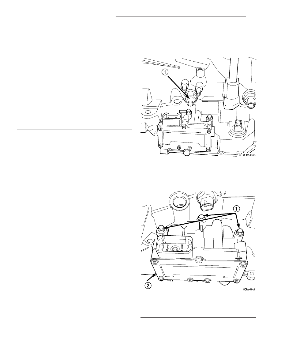
(5) Remove input speed sensor (Fig. 305).
(6) Remove
three
(3)
solenoid/pressure
switch
assembly-to-transaxle case bolts (Fig. 306).
(7) Remove solenoid/pressure switch assembly and
gasket (Fig. 307). Use care to prevent gasket mate-
rial and foreign objects from become lodged in the
transaxle case ports.
Fig. 305 Input Speed Sensor
1 - INPUT SPEED SENSOR
Fig. 306 Solenoid/Pressure Switch Assembly-to-
Case Bolts
1 - BOLTS
2 - SOLENOID AND PRESSURE SWITCH ASSEMBLY
21 - 238
41TE AUTOMATIC TRANSAXLE
RS
SOLENOID/PRESSURE SWITCH ASSY (Continued)