Chrysler Town, Dodge Caravan. Manual - part 337


  Index      Chrysler     Chrysler TOWN & COUNTRY, VOYAGER, Dodge Caravan - service repair manual 2001-2007 year


Search            


Content   ..  335  336  337  338   ..


Chrysler Town, Dodge Caravan. Manual - part 337


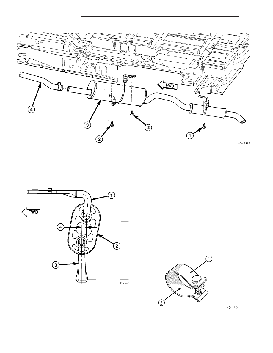
(4) Insert muffler pipe into catalytic converter pipe

until the hangers are positioned as shown in (Fig. 11)

CAUTION: Band clamps should never be tightened
such that the two sides of the clamps are bottomed
out against the center hourglass shaped center

block. Once this occurs, the clamp band has been
stretched and has lost its clamping force and must
be replaced.
To replace the band clamp; remove the nut and peel
back the ends of the clamp until spot weld breaks.
Clean remaining spot weld from the pipe using a
file or grinder until surface is smooth.

NOTE: Maintain proper clamp orientation when
replacing with new clamp.

(5) Tighten the band clamp to 55 N·m (40 ft. lbs.)

(Fig. 12).

(6) Connect the right side half shaft to the rear

differential module (AWD equipped only).

Fig. 10 Exhaust System - Typical (All Vehicles)

1 - SCREW - RESONATOR HANGER TO BODY

3 - MUFFLER & RESONATOR ASSEMBLY

2 - SCREW - MUFFLER HANGER TO BODY

4 - CATALYTIC CONVERTER PIPE

Fig. 11 Exhaust System Alignment

1 - HANGER BRACKET TO BODY
2 - ISOLATOR
3 - HANGER - MUFFLER/RESONATOR SUPPORT
4 - 6 mm (0.25 in.)

Fig. 12 Band Clamp

1 - BAND CLAMP
2 - TORQUE SPECIFICATION

11 - 8

EXHAUST SYSTEM

RS

MUFFLER (Continued)

RESONATOR

REMOVAL

(1) (Refer to 11 - EXHAUST SYSTEM/MUFFLER -

REMOVAL)

INSTALLATION

(1) (Refer to 11 - EXHAUST SYSTEM/MUFFLER -

INSTALLATION)

RS

EXHAUST SYSTEM

11 - 9

FRAME & BUMPERS

TABLE OF CONTENTS

page

page

BUMPERS

SPECIFICATIONS - TORQUE

. . . . . . . . . . . . . . . 1

FRONT FASCIA

REMOVAL

. . . . . . . . . . . . . . . . . . . . . . . . . . . . . 1

INSTALLATION

. . . . . . . . . . . . . . . . . . . . . . . . . . 1

FRONT BUMPER REINFORCEMENT

REMOVAL

. . . . . . . . . . . . . . . . . . . . . . . . . . . . . 2

INSTALLATION

. . . . . . . . . . . . . . . . . . . . . . . . . . 2

REAR FASCIA

REMOVAL

. . . . . . . . . . . . . . . . . . . . . . . . . . . . . 2

INSTALLATION

. . . . . . . . . . . . . . . . . . . . . . . . . . 2

REAR BUMPER REINFORCEMENT

REMOVAL

. . . . . . . . . . . . . . . . . . . . . . . . . . . . . 3

INSTALLATION

. . . . . . . . . . . . . . . . . . . . . . . . . . 3

REAR FASCIA - SCUFF PAD

REMOVAL

. . . . . . . . . . . . . . . . . . . . . . . . . . . . . 3

INSTALLATION

. . . . . . . . . . . . . . . . . . . . . . . . . . 4

FRAME

SPECIFICATIONS

FRAME DIMENSIONS

. . . . . . . . . . . . . . . . . . . 4

SPECIFICATIONS - TORQUE

. . . . . . . . . . . . . 4

FRONT CRADLE CROSSMEMBER

DESCRIPTION

DESCRIPTION - FRONT CRADLE

CROSSMEMBER . . . . . . . . . . . . . . . . . . . . . . . 9

DESCRIPTION - FRONT CRADLE

CROSSMEMBER THREAD REPAIR . . . . . . . . . 9

REMOVAL

. . . . . . . . . . . . . . . . . . . . . . . . . . . . . 9

INSTALLATION

. . . . . . . . . . . . . . . . . . . . . . . . . 11

FRONT CROSSMEMBER MOUNT BUSHINGS

REMOVAL

. . . . . . . . . . . . . . . . . . . . . . . . . . . . . 12

INSTALLATION

. . . . . . . . . . . . . . . . . . . . . . . . . 12

BUMPERS

SPECIFICATIONS - TORQUE

DESCRIPTION

N·m

Ft. Lbs.

In. Lbs.

Front bumper reinforcement attaching nut

54

40

Rear bumper reinforcement attaching nut

27

20

FRONT FASCIA

REMOVAL

(1) Release hood latch and open hood.
(2) Remove the headlamp assemblies (Refer to 8 -

ELECTRICAL/LAMPS/LIGHTING

-

EXTERIOR/

HEADLAMP - REMOVAL).

(3) Hoist vehicle and support with safety stands.
(4) Remove the five bolts attaching bottom of fas-

cia/air dam to radiator closure panel.

(5) Remove front wheels.
(6) Remove front wheelhouse splash shields fasten-

ers as necessary to gain access to bolts attaching
front fascia to fender. (Refer to 23 - BODY/EXTERI-
OR/ WHEELHOUSE SPLASH SHIELD - REMOV-
AL).

(7) Remove the two bolts and two nuts attaching

fascia to the front fenders (Fig. 1).

(8) Disconnect fog lamp wire connectors, if neces-

sary.

(9) Lower vehicle.

(10) Remove two bolts attaching the upper grille

support to the headlamp mounting panel at each side
of the grille.

(11) Remove bumper fascia from vehicle.

INSTALLATION

(1) Position front bumper fascia on vehicle.
(2) Install the two bolts attaching fascia to head-

lamp mounting panel at each side of grille.

(3) Hoist vehicle and support with safety stands.
(4) Install the two bolts and two nuts attaching

fascia to the front fenders (Fig. 1). The fascia should
be flush to fender.

(5) Install front wheelhouse splash shields fasten-

ers. (Refer to 23 - BODY/EXTERIOR/ WHEEL-
HOUSE SPLASH SHIELD - INSTALLATION).

(6) Install front wheels.
(7) Connect fog lamp wire connectors, if necessary.
(8) Install the five bolts attaching bottom of fascia

to radiator closure panel.

(9) Lower the vehicle.

RS

FRAME & BUMPERS

13 - 1


Content   ..  335  336  337  338   ..