Chrysler Town, Dodge Caravan. Manual - part 313


  Index      Chrysler     Chrysler TOWN & COUNTRY, VOYAGER, Dodge Caravan - service repair manual 2001-2007 year


Search            


Content   ..  311  312  313  314   ..


Chrysler Town, Dodge Caravan. Manual - part 313


BALANCE SHAFT CARRIER

The following components will remain intact dur-

ing carrier removal: Gear cover, gears, balance shafts
and the rear cover (Fig. 130).

(1) Drain engine oil.
(2) Remove the oil pan and pick-up tube (Refer to

9 - ENGINE/LUBRICATION/OIL PAN - REMOVAL).

(3) Remove chain cover, guide and tensioner (Fig.

131).

(4) Remove screw retaining balance shaft drive

sprocket (Fig. 132).

(5) Move balance shaft inboard through drive

chain sprocket. Sprocket will hang in lower chain
loop.

(6) Remove carrier to crankcase attaching bolts to

remove carrier.

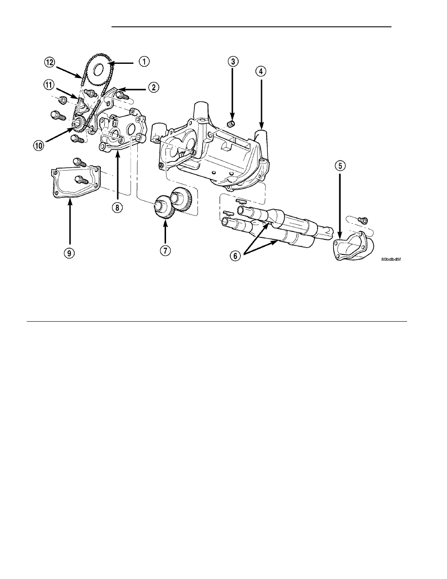
Fig. 130 Balance Shafts and Carrier Assembly

1 - SPROCKET

7 - GEARS

2 - TENSIONER

8 - GEAR COVER

3 - PLUG

9 - CHAIN COVER

4 - CARRIER

10 - SPROCKET

5 - REAR COVER

11 - GUIDE

6 - BALANCE SHAFTS

12 - CHAIN

9 - 70

ENGINE 2.4L

RS

BALANCE SHAFTS AND CARRIER ASSEMBLY (Continued)

Fig. 131 Chain Cover, Guide and Tensioner

1 - STUD
2 - TENSIONER (ADJUSTER)
3 - GEAR COVER
4 - ADJUST SCREW
5 - PIVOT SCREW
6 - CHAIN COVER (CUTAWAY)
7 - GUIDE

Fig. 132 Drive Chain and Sprockets

1 - NICKEL PLATED LINK AND MARK
2 - GEAR/SPROCKET SCREWS
3 - NICKEL PLATED LINK AND DOT

Fig. 133 Gear Cover and Gears

1 - STUD (DOUBLE ENDED)
2 - DRIVE GEAR
3 - DRIVEN GEAR
4 - CARRIER DOWEL
5 - GEAR(S)
6 - GEAR COVER

Fig. 134 Balance Shaft - Removal/Installation

1 - REAR COVER
2 - CARRIER
3 - BALANCE SHAFT

RS

ENGINE 2.4L

9 - 71

BALANCE SHAFTS AND CARRIER ASSEMBLY (Continued)

INSTALLATION

BALANCE SHAFT INSTALLATION/TIMING

Balance shaft and carrier assembly installation is

the reverse of the removal procedure. During instal-
lation crankshaft-to-balance shaft timing must
be established. Refer to Timing procedure in
this section.

(1) With balance shafts installed in carrier (Fig.

130) position carrier on crankcase and install four
attaching bolts and tighten to 54 N·m (40 ft. lbs.).

(2) Turn balance shafts until both shaft key ways

are up, parallel to vertical centerline of engine.
Install short hub drive gear on sprocket driven shaft
and long hub gear on gear driven shaft. After instal-
lation gear and balance shaft keyways must be up
with gear timing marks meshed as shown in (Fig.
135).

(3) Install gear cover and tighten double ended

stud/washer fastener to 12 N·m (105 in. lbs.).

(4) Align flat on balance shaft drive sprocket to the

flat on crankshaft (Fig. 136).

(5) Install balance shaft drive sprocket on crank-

shaft using Special Tool 6052 (Fig. 137).

(6) Turn crankshaft until number 1 cylinder is at

top dead center (TDC). The timing marks on the
chain sprocket should line up with the parting line
on the left side of number one main bearing cap.
(Fig. 138).

(7) Place chain over crankshaft sprocket so that

the plated link of the chain is over the number 1 cyl-
inder timing mark on the balance shaft crankshaft
sprocket (Fig. 138).

(8) Place balance shaft sprocket into the timing

chain (Fig. 138) and align the timing mark on the
sprocket (dot) with the (lower) plated link on the
chain.

NOTE: The lower plated link is 8 links from the
upper link.

Fig. 135 Gear Timing

1 - KEY WAYS UP
2 - GEAR ALIGNMENT DOTS

Fig. 136 Balance Shaft Sprocket Alignment to

Crankshaft

1 - ALIGN FLATS

Fig. 137 Balance Shaft Drive

1 - SPROCKET
2 - SPECIAL TOOL 6052

9 - 72

ENGINE 2.4L

RS

BALANCE SHAFTS AND CARRIER ASSEMBLY (Continued)

(9) With balance shaft keyways pointing up (12

o’clock) slide the balance shaft sprocket onto the nose
of the balance shaft. The balance shaft may have to
be pushed in slightly to allow for clearance.

NOTE: THE TIMING MARK ON THE SPROCKET, THE
(LOWER) NICKEL PLATED LINK, AND THE ARROW
ON THE SIDE OF THE GEAR COVER SHOULD LINE
UP WHEN THE BALANCE SHAFTS ARE TIMED
CORRECTLY.

(10) If the sprockets are timed correctly, install the

balance shaft bolts and tighten to 28 N·m (250 in.
lbs.). A wood block placed between crankcase and
crankshaft counterbalance will prevent crankshaft
and gear rotation.

(11) CHAIN TENSIONING:

(a) Install chain tensioner loosely assembled.
(b) Position guide on double ended stud making

sure tab on the guide fits into slot on the gear
cover. Install and tighten nut/washer assembly to
12 N·m (105 in. lbs.).

(c) Place a shim 1 mm (0.039 in.) thick x 70 mm

(2.75 in.) long between tensioner and chain. Push
tensioner and shim up against the chain. Apply
firm pressure 2.5–3 Kg (5.5–6.6 lbs.) directly
behind the adjustment slot to take up all
slack. 
Chain must have shoe radius contact as
shown in (Fig. 139).

(d) With the load applied, tighten top tensioner

bolt first, then bottom pivot bolt. Tighten bolts to
12 N·m (105 in. lbs.). Remove shim.

(e) Install carrier covers and tighten screws to

12 N·m (105 in. lbs.).
(12) If removed, install oil pump (Refer to 9 -

ENGINE/LUBRICATION/OIL PUMP - INSTALLA-
TION).

(13) Install pick-up tube and oil pan (Refer to 9 -

ENGINE/LUBRICATION/OIL

PAN

-

INSTALLA-

TION).

(14) Fill engine crankcase with proper oil to cor-

rect level.

Fig. 138 Balance Shaft Timing

1 - MARK ON SPROCKET
2 - KEYWAYS UP
3 - ALIGN MARKS
4 - PLATED LINK
5 - PARTING LINE (BEDPLATE TO BLOCK)
6 - PLATED LINK

Fig. 139 Chain Tension Adjustment

1 - 1MM (0.039 IN.) SHIM
2 - TENSIONER (ADJUSTER) BOLT
3 - PIVOT BOLT

RS

ENGINE 2.4L

9 - 73

BALANCE SHAFTS AND CARRIER ASSEMBLY (Continued)


Content   ..  311  312  313  314   ..