Chrysler Town, Dodge Caravan. Manual - part 312


  Index      Chrysler     Chrysler TOWN & COUNTRY, VOYAGER, Dodge Caravan - service repair manual 2001-2007 year


Search            


Content   ..  310  311  312  313   ..


Chrysler Town, Dodge Caravan. Manual - part 312


ting notch and spring tang should remain aligned
after lock nut is torqued.

(6) Remove allen wrench and torque wrench.

NOTE: Repositioning the crankshaft to the TDC
position must be done only during the CLOCKWISE
rotation movement. If TDC is missed, rotate a fur-
ther two revolutions until TDC is achieved. DO NOT
rotate crankshaft counterclockwise as this will
make verification of proper tensioner setting impos-
sible.

(7) Rotate the crankshaft CLOCKWISE two com-

plete revolutions manually for seating of the belt,
until the crankshaft is repositioned at the TDC posi-
tion. Verify that the camshaft and crankshaft timing
marks are in proper position (Fig. 124).

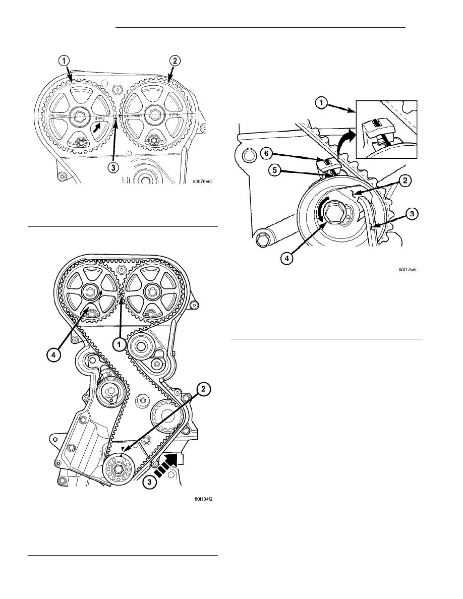
Fig. 121 Camshaft Sprocket Alignment

1 - CAMSHAFT SPROCKET-EXHAUST
2 - CAMSHAFT SPROCKET-INTAKE
3 - 1/2 NOTCH LOCATION

Fig. 122 Timing Belt Installation

1 - CAMSHAFT TIMING MARKS 1/2 NOTCH LOCATION
2 - CRANKSHAFT AT TDC
3 - INSTALL BELT IN THIS DIRECTION
4 - ROTATE CAMSHAFT SPROCKET TO TAKE UP BELT SLACK

Fig. 123 Timing Belt Tension Adjustment

1 - ALIGN SETTING NOTCH WITH SPRING TANG
2 - TOP PLATE
3 - 6mm ALLEN WRENCH
4 - LOCK BOLT
5 - SETTING NOTCH
6 - SPRING TANG

9 - 66

ENGINE 2.4L

RS

TIMING BELT AND SPROCKET(S) (Continued)

(8) Check if the spring tang is within the tolerance

window (Fig. 125). If the spring tang is within the
tolerance window, the installation process is complete
and nothing further is required. If the spring tang is
not within the tolerance window, repeat Steps 5
through 7.

(9) Install engine mount bracket to engine (Fig.

115).

(10) Install timing belt front covers and bolts

(Refer to 9 - ENGINE/VALVE TIMING/TIMING
BELT COVER(S) - INSTALLATION).

(11) Install air conditioning/generator belt ten-

sioner and pulley (Refer to 7 - COOLING/ACCES-
SORY

DRIVE/BELT

TENSIONERS

-

INSTALLATION).

(12) Install right engine mount (Refer to 9 -

ENGINE/ENGINE MOUNTING/RIGHT MOUNT -
INSTALLATION).

(13) Install crankshaft vibration damper (Refer to

9

-

ENGINE/ENGINE

BLOCK/VIBRATION

DAMPER - INSTALLATION).

(14) Install accessory drive belts (Refer to 7 -

COOLING/ACCESSORY

DRIVE/DRIVE

BELTS

-

INSTALLATION).

(15) Install drive belt splash shield.
(16) Install right front wheel.
(17) Connect make-up air hose to cylinder head

cover.

(18) Install air cleaner housing, upper cover, and

clean air tube.

Fig. 124 Crankshaft and Camshaft Timing

1 - CAMSHAFT TIMING MARKS
2 - CRANKSHAFT TDC MARKS
3 - TRAILING EDGE OF SPROCKET TOOTH

Fig. 125 Timing Belt Tension Verification

1 - SPRING TANG
2 - TOLERANCE WINDOW

RS

ENGINE 2.4L

9 - 67

TIMING BELT AND SPROCKET(S) (Continued)

TIMING BELT TENSIONER &
PULLEY

REMOVAL

(1) Remove the timing belt (Refer to 9 - ENGINE/

VALVE TIMING/TIMING BELT AND SPROCKETS -
REMOVAL).

(2) Remove timing belt idler pulley (Fig. 126).

(3) Hold camshaft sprocket with Special Tool 6847

while removing bolt (Fig. 127). Remove both cam
sprockets.

(4) Remove rear timing belt cover fasteners and

remove cover from engine (Fig. 128).

(5) Remove lower bolt attaching timing belt ten-

sioner assembly to engine and remove tensioner as
an assembly 
(Fig. 129).

Fig. 126 Timing Belt Idler Pulley

1 - IDLER PULLEY
2 - BOLT

Fig. 127 Camshaft Sprocket - Removal/Installation

1 - SPECIAL TOOL 6847

Fig. 128 Rear Timing Belt Cover Fasteners

1 - M6 BOLTS - 12 N·m (105 in. lbs.)
2 - M8 BOLTS - 28 N·m (250 in. lbs.)
3 - TIMING BELT TENSIONER

9 - 68

ENGINE 2.4L

RS

INSTALLATION

(1) Align timing belt tensioner assembly to engine

and install lower mounting bolt but do not tighten
(Fig. 129). To properly align tensioner assembly—in-
stall one of the engine bracket mounting bolts (M10)
5 to 7 turns into the tensioner’s upper mounting loca-
tion (Fig. 129).

(2) Torque the tensioner’s lower mounting bolt to

61 N·m (45 ft. lbs.). Remove the upper bolt used for
tensioner alignment.

(3) Install rear timing belt cover and fasteners.

Torque fasteners to values specified in (Fig. 128).

(4) Install timing belt idler pulley and torque

mounting bolt to 61 N·m (45 ft. lbs.) (Fig. 126).

(5) Install camshaft sprockets. Use Special Tool

6847 to hold sprockets (Fig. 127), torque bolts to 101
N·m (75 ft. lbs.).

(6) Install the timing belt (Refer to 9 - ENGINE/

VALVE TIMING/TIMING BELT AND SPROCKETS -
INSTALLATION).

BALANCE SHAFTS AND
CARRIER ASSEMBLY

DESCRIPTION

The 2.4L engine is equipped with two nodular cast

iron balance shafts installed in a cast aluminum car-
rier attached to the lower cylinder block (Fig. 130).

OPERATION

The balance shafts are driven by the crankshaft

via a roller chain and sprockets. The balance shafts
are connected by helical gears. The dual counter
rotating shafts decrease second order vertical shak-
ing forces caused by component movement.

REMOVAL

BALANCE SHAFTS/CHAIN/SPROCKETS

NOTE: For service procedures requiring only tem-
porary relocation of carrier assembly refer to BAL-
ANCE SHAFT CARRIER procedure below.

(1) Drain engine oil.
(2) Remove the oil pan and pick-up tube (Refer to

9 - ENGINE/LUBRICATION/OIL PAN - REMOVAL).

(3) If replacing crankshaft sprocket, remove oil

pump (Refer to 9 - ENGINE/LUBRICATION/OIL
PUMP - REMOVAL).

(4) Remove chain cover, guide and tensioner (Fig.

131).

(5) Remove screw retaining balance shaft drive

sprocket (Fig. 132). Remove chain and sprocket.

(6) Using two wide pry bars, work the crankshaft

sprocket back and forth until it is off the crankshaft-
shaft.

(7) Remove gear cover retaining stud (double

ended to also retain chain guide). Remove cover and
balance shaft gears (Fig. 133).

(8) Remove rear cover and balance shafts (Fig.

134).

(9) Remove four carrier to crankcase attaching

bolts to separate carrier from engine bedplate.

Fig. 129 Timing Belt Tensioner/Bracket Assembly

1 - BOLT
2 - TENSIONER ASSEMBLY
3 - BOLT-INSTALL FOR PROPER ALIGNMENT

RS

ENGINE 2.4L

9 - 69

TIMING BELT TENSIONER & PULLEY (Continued)


Content   ..  310  311  312  313   ..