Chrysler Town, Dodge Caravan. Manual - part 299


  Index      Chrysler     Chrysler TOWN & COUNTRY, VOYAGER, Dodge Caravan - service repair manual 2001-2007 year


Search            


Content   ..  297  298  299  300   ..


Chrysler Town, Dodge Caravan. Manual - part 299


(18) Remove axle shafts. (Refer to 3 - DIFFEREN-

TIAL & DRIVELINE/HALF SHAFT - REMOVAL)

(19) Drain engine oil and remove oil filter. (Refer

to 9 - ENGINE/LUBRICATION/OIL - STANDARD
PROCEDURE)

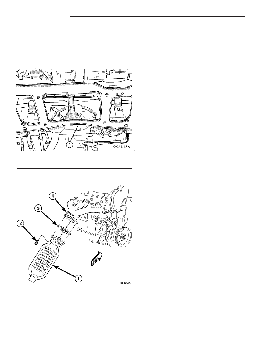
(20) Remove crossmember cradle plate (Fig. 6).

(21) Disconnect exhaust pipe from manifold (Fig.

7).

(22) Remove engine front mount and bracket from

engine. (Refer to 9 - ENGINE/ENGINE MOUNTING/
FRONT MOUNT - REMOVAL)

(23) Remove

structural

collar.

(Refer

to

9

-

ENGINE/ENGINE BLOCK/STRUCTURAL COVER -
REMOVAL)

(24) Remove rear engine mount bracket. (Refer to

9 - ENGINE/ENGINE MOUNTING/REAR MOUNT -
REMOVAL)

(25) Mark flex plate to torque converter and

remove torque converter bolts.

(26) Pinch-off power steering supply hose at pump.

Remove hose from pump.

(27) Remove and set aside the power steering

pump and bracket. Do not disconnect pressure line.

(28) Lower vehicle.
(29) Remove A/C lines at compressor and cap open-

ings.

(30) Remove engine ground straps (strap at engine

right mount and at starter).

(31) Raise vehicle enough to allow engine dolly

Special Tool 6135, cradle Special Tool 6710 with
Posts Special Tool 6848 to be installed under vehicle
(Fig. 8).

(32) Loosen cradle posts to allow movement for

proper positioning. Locate two rear posts (right side
of engine) into the holes on the engine bedplate.
Locate the two front posts (left side of engine) on the
oil pan rails (Fig. 8). Lower vehicle and position cra-
dle mounts until the engine is resting on mounts.
Tighten mounts to cradle frame. This will keep
mounts from moving when removing or installing
engine and transmission.

(33) Install safety straps around the engine to cra-

dle. Tighten straps and lock.

(34) Lower vehicle so the weight of ONLY THE

ENGINE AND TRANSMISSION are on the cradle.

(35) Remove engine and transmission mount bolts.
(36) Raise vehicle slowly. It may be necessary to

move the engine/transmission assembly with the
dolly to allow for removal around the body.

Fig. 6 Crossmember Cradle Plate

1 - CRADLE PLATE

Fig. 7 Catalytic Converter to Exhaust Manifold

1 - CATALYTIC CONVERTER
2 - BOLT
3 - GASKET
4 - FLAG NUT

9 - 14

ENGINE 2.4L

RS

ENGINE 2.4L (Continued)

Fig. 8 Positioning Engine Cradle Support Post Mounts

1 - SPECIAL TOOL POSTS 6848

4 - SPECIAL TOOL 6710 CRADLE

2 - SPECIAL TOOL 6135 DOLLY

5 - SPECIAL TOOL 6848 - POST CONTACT ON PAN RAIL

3 - SPECIAL TOOL POSTS 6848

RS

ENGINE 2.4L

9 - 15

ENGINE 2.4L (Continued)

INSTALLATION - ENGINE ASSEMBLY

(1) Position engine and transmission assembly

under vehicle and slowly lower the vehicle over the
engine and transmission.

(2) Align

engine

and

transmission

mounts

to

attaching points. Install mounting bolts at the right
(Fig. 9) and left mounts (Fig. 10).

(3) Remove safety straps.
(4) Slowly raise vehicle enough to remove the

engine dolly and cradle Special Tools 6135 and 6710.

(5) Install rear mount bracket and rear mount

through

bolt.

(Refer

to

9

-

ENGINE/ENGINE

MOUNTING/REAR MOUNT - INSTALLATION)

(6) Install the flex plate to torque converter bolts.
(7) Install structural collar. (Refer to 9 - ENGINE/

ENGINE BLOCK/STRUCTURAL COVER - INSTAL-
LATION)

(8) Install front mount bracket and front mount

through

bolt.

(Refer

to

9

-

ENGINE/ENGINE

MOUNTING/FRONT MOUNT - INSTALLATION)

(9) Connect exhaust system to manifold (Fig. 7).
(10) Install crossmember cradle plate (Fig. 6).
(11) Install new oil filter.
(12) Install power steering pump and bracket.
(13) Connect power steering supply line to pump

and remove pinch-off pliers.

(14) Connect A/C compressor hoses to compressor.
(15) Install accessory drive belts. (Refer to 7 -

COOLING/ACCESSORY

DRIVE/DRIVE

BELTS

-

INSTALLATION)

(16) Install axle shafts. (Refer to 3 - DIFFEREN-

TIAL & DRIVELINE/HALF SHAFT - INSTALLA-
TION)

(17) Install accessory drive belt splash shield.
(18) Install front wheels and tires.
(19) Remove plugs from transmission cooler hoses

and install transaxle oil cooler line service splice kit.
Refer to instructions included with kit.

(20) Connect the transaxle shift linkage and elec-

trical connectors.

(21) Connect heater hoses (Fig. 5).
(22) Install ground straps.
(23) Connect all engine and throttle body electrical

connections.

(24) Connect all vacuum lines.
(25) Connect the throttle cables.
(26) Connect the fuel line. (Refer to 14 - FUEL

SYSTEM/FUEL DELIVERY/QUICK CONNECT FIT-
TING - STANDARD PROCEDURE)

(27) Connect radiator lower and upper hoses.
(28) Install radiator fans. (Refer to 7 - COOLING/

ENGINE/RADIATOR FAN - INSTALLATION)

(29) Fill cooling system. (Refer to 7 - COOLING -

STANDARD PROCEDURE)

(30) Connect battery cables.
(31) Install air cleaner and inlet hose.
(32) Fill engine crankcase with proper oil to cor-

rect level.

Fig. 9 RIGHT MOUNT TO RAIL AND ENGINE

1 - BOLT - MOUNT TO RAIL 68 N·m (50 ft. lbs.)
2 - BOLT - MOUNT TO ENGINE 54 N·m (40 ft. lbs.)
3 - BOLT - MOUNT TO RAIL (HORIZONTAL) 68 N·m (50 ft. lbs.)
4 - RIGHT ENGINE MOUNT
5 - RIGHT FRAME RAIL

Fig. 10 LEFT MOUNT TO FRAME BRACKET

1 - FRAME BRACKET
2 - FRAME RAIL - LEFT
3 - BOLT
4 - TRANSAXLE MOUNT

9 - 16

ENGINE 2.4L

RS

ENGINE 2.4L (Continued)

(33) Start engine and run until operating temper-

ature is reached.

(34) Adjust transmission linkage, if necessary.

SPECIFICATIONS

SPECIFICATIONS - 2.4L ENGINE

DESCRIPTION

SPECIFICATION

General Specification

Type

In-Line OHV, DOHC

Number of Cylinders

4

Displacement

2.4 Liters

(148 cu. in.)

Bore

87.5 mm

(3.445 in.)

Stroke

101.0 mm

(3.976 in.)

Compression Ratio

9.4:1

Firing Order

1-3-4-2

Compression Pressure

690 kPa (Minimum)

(100 psi Minimum)

Max. Variation Between
Cylinders

25%

Cylinder Block

Cylinder Bore Diameter

87.4924–87.5076 mm

(3.4446–3.4452 in.)

Out-of-Round (Max.)

0.051 mm

(0.002 in.)

Taper (Max.)

0.051 mm

(0.002 in.)

Pistons

Piston Diameter

87.463–87.481 mm

(3.4434–3.4441 in.)

Clearance @ 14 mm
(9/16 in.) from bottom of
skirt

0.024–0.057 mm

(0.0009–0.0022 in.)

Weight

346–356 grams

(12.20–12.56 oz.)

Land Clearance
(Diametrical)

0.614–0.664 mm

(0.024–0.026 in.)

Piston Length

66.25 mm

(2.608 in.)

Piston Ring Groove
Depth No. 1

4.640–4.784 mm

(0.182–0.188 in.)

DESCRIPTION

SPECIFICATION

Piston Ring Groove
Depth No. 2

4.575–4.719 mm

(0.180–0.185 in.)

Piston Ring Groove
Depth No. 3

4.097–4.236 mm

(0.161–0.166 in.)

Piston Pins

Clearance in Piston

0.005–0.018 mm

(0.0002–0.0008 in.)

Clearance in Connecting
Rod

Interference

Diameter

21.998–22.003 mm

(0.8660–0.8662 in.)

End Play

None

Length

72.75–73.25 mm

(2.864–2.883 in.)

Piston Rings

Ring Gap—Top
Compression Ring

0.25–0.51 mm

(0.0098–0.020 in.)

Wear Limit

0.8 mm

(0.031 in.)

Ring Gap—2nd
Compression Ring

0.23–0.48 mm

(0.009–0.018 in.)

Wear Limit

0.8 mm

(0.031 in.)

Ring Gap—Oil Control
Steel Rails

0.25–0.64 mm

(0.0098–0.025 in.)

Wear Limit

1.0 mm

(0.039 in.)

Ring Side Clearance—
Compression Rings

0.030–0.080 mm

(0.0011–0.0031 in.)

Wear Limit

0.10 mm

(0.004 in.)

Ring Side Clearance—Oil
Ring Pack

0.012–0.178 mm

(0.0004–0.0070 in.)

Ring Width—
Compression Rings

1.47–1.50 mm

(0.057–0.059 in.)

Ring Width—Oil Ring
Pack

2.72–2.88 mm

(0.107–0.1133 in.)

Connecting Rod

Bearing Clearance

0.025–0.071 mm

(0.0009–0.0027 in.)

Wear Limit

0.075 mm

(0.003 in.)

RS

ENGINE 2.4L

9 - 17

ENGINE 2.4L (Continued)


Content   ..  297  298  299  300   ..