Chrysler Town, Dodge Caravan. Manual - part 118
INSTALLATION
(1) Connect the liftgate lock cylinder link rod on
the cinch latch assembly. Rotate the plastic retaining
clip 90 ° to lock retaining clip on linkrod.
(2) Connect the link rod on the lock cylinder.
(3) Install three new power latch retaining bolts.
Torque to 10 N·m (90 in. lbs.).
(4) Connect the power latch electrical connector
and secure push pin retainers.
(5) Connect the negative battery cable.
(6) Using an appropriate scan tool, check and
erase any power liftgate control module diagnostic
trouble codes related to the power latch.
(7) Verify power liftgate system and power cinch /
release latch operation. Cycle the power liftgate
through one complete open and close cycle, this will
allow the power liftgate control module to relearn its
cycle with the new components.
(8) Verify power liftgate manual operation. Using
liftgate key rotate the lock cylinder to verify door
operation. Pull door open using exterior liftgate han-
dle / switch.
(9) Install the liftgate trim panel. Refer to Body for
the procedure.
LATCH ACTUATOR
DESCRIPTION
Vehicles equipped with a power liftgate utilize a
power cinch latch or power release latch (Fig. 10).
The power cinch and/or power release is made possi-
ble by a latch actuator attached to the leading edge
of the power latch assembly. This 12 volt latch actua-
tor contains a small drive gear that meshes with the
latch assemblies internal gears to perform the power
cinch close / power release operations. Refer to the
Latch assembly for more information.
The power cinch/release actuator is serviceable
component. Consult your Mopar™ parts catalog for
specific part numbers.
OPERATION
During a power close cycle, the power cinch actua-
tor provides the torque required to close the power
liftgate from the secondary to the primary closed and
latched position. During a power open cycle, the
power release actuator releases the liftgate from the
primary closed and latched position to the fully
unlatched and movable position.
REMOVAL
(1) Disconnect and isolate the negative battery
cable.
(2) Open the liftgate and remove the lower liftgate
trim panel. Refer to Body for the procedure.
(3) Disconnect the power latch electrical connector
(Fig. 10).
(4) Remove the three latch retaining bolts.
(5) Grab the latch assembly and unhook the key
cylinder link rod from the key cylinder (Fig. 10).
(6) Place the latch assembly on a bench and locate
the three wires leading from the actuator portion of
the latch assembly.
(7) Disengage the main connector retaining push
pins from the latch actuator housing.
(8) Back the three wires out of the main latch elec-
trical connector. Refer to the wiring section of the
service manual for detailed instructions.
(9) Flip the latch assembly over and remove the
latch actuator retaining screw(s).
(10) Remove the latch actuator from the latch
assembly.
INSTALLATION
(1) Install the latch actuator on the latch assem-
bly.
(2) Install
the
three
latch
actuator
retaining
screws. Torque the screws to 4 in. lbs.
(3) Install the three wires in the main latch elec-
trical connector. Refer to the wiring section of the
service manual for detailed instructions.
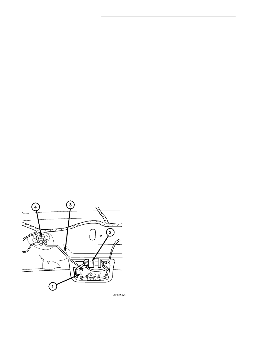
Fig. 10 POWER LATCH ORIENTATION
1 - LATCH & ACTUATOR ASSEMBLY
2 - LATCH ELECTRICAL CONNECTOR
3 - LOCK CYLINDER LINK ROD
4 - LIFTGATE LOCK CYLINDER
8N - 14
POWER LIFTGATE SYSTEM
RS
LATCH (Continued)