Content .. 1108 1109 1110 1111 ..
Chrysler Town, Dodge Caravan. Manual - part 1110
OPERATION
The intake air temperature sensor is a negative
temperature coefficient (NTC) thermistor (resistance
varies inversly with temperature). This means at
cold air temperature its resistance is high, so the
voltage signal will be high. As intake air temperature
increases, sensor resistance decreases and the signal
voltage will be low. This allows the sensor to provide
an analog voltage signal (0.2-4.8 volts) to the ECM.
REMOVAL
(1) Disconnect negative battery cable.
(2) Remove engine cover retaining bolts and cover-
(Refer to 9 - ENGINE - REMOVAL).
(3) Disconnect intake air temperature electrical
connector.
(4) Remove intake air temperature sensor retain-
ing screws and sensor (Fig. 8).
INSTALLATION
(1) Install intake air temperature sensor and
retaining bolts (Fig. 8). Torque to 5.4 N·m.
(2) Connect intake air temperature sensor.
(3) Install engine cover and retaining bolts (Refer
to 9 - ENGINE - INSTALLATION).
CRANKSHAFT POSITION
SENSOR
DESCRIPTION
The crankshaft position sensor is mounted in the
right rear of the engine block below the turbocharger
(Fig. 9). This sensor is used to detect engine speed.
OPERATION
The crankshaft position sensor is a magnetic
pickup type sensor that generates an A/C signal. The
sensor contains a permanent magnet and a coil of
wire. The sensor generates an A/C signal each time a
notch in the reluctor wheel on the crankshaft passes
across the permanent magnet. The ECM calculates
engine speed based on the frequency of the A/C sig-
nal.
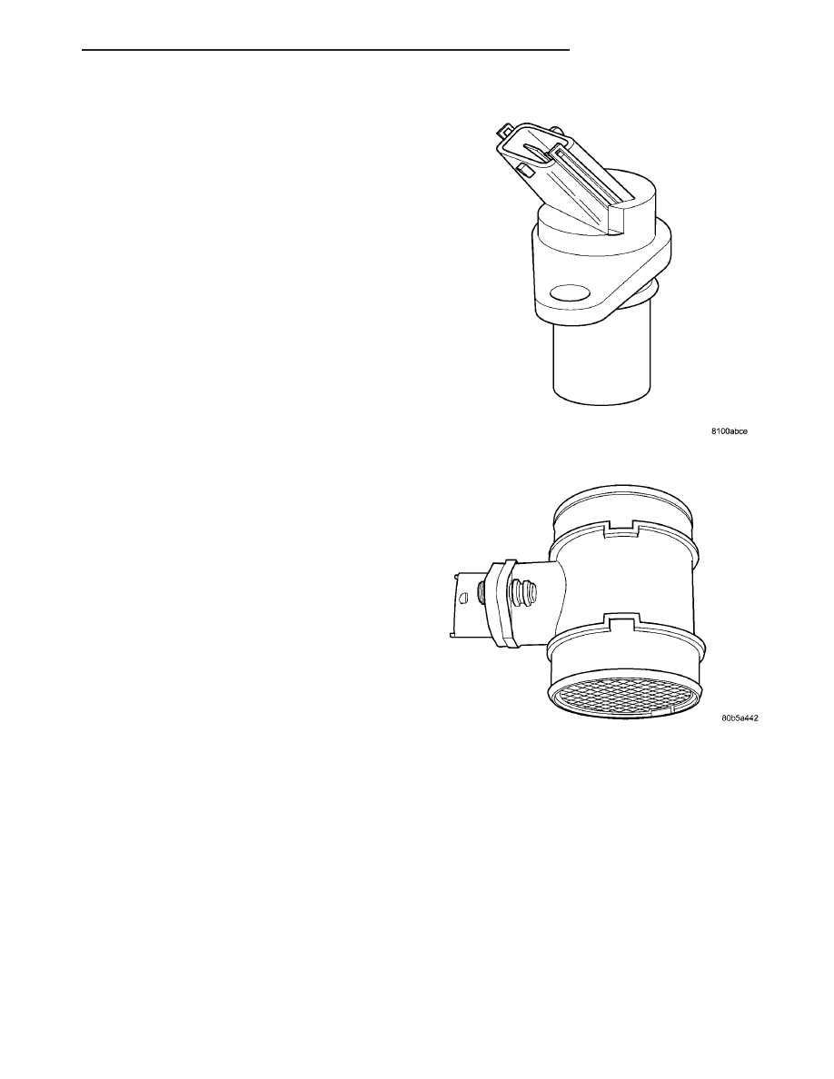
MASS AIR FLOW (MAF)
SENSOR
DESCRIPTION
The Mass Air Flow (MAF) Sensor is mounted
inline in the air intake between the air filter and the
turbocharger (Fig. 10).
OPERATION
The ECM uses the mass air flow (MAF) sensor to
measure air density. The MAF sensor contains a
ceramic element. A signal voltage is provided to the
element. As engine speed increases, airflow across
the ceramic element increases. Changes in air flow
and air density cause the temperature of the ceramic
element to fluxuate. The ceramic element changes
resistance respectively to changes in temperature.
The change in resistance varies the signal voltage
output to the ECM. The ECM/PCM relay supplies
battery power the to MAF sensor. Ground is provided
by the ECM. The MAF sensor signal is provided by
the ECM.
Fig. 9 CRANKSHAFT POSITION SENSOR
Fig. 10 MASS AIR FLOW (MAF) SENSOR
RG
FUEL INJECTION
14 - 23
INTAKE AIR TEMPERATURE SENSOR (Continued)