Chrysler Town, Dodge Caravan. Manual - part 1106


  Index      Chrysler     Chrysler TOWN & COUNTRY, VOYAGER, Dodge Caravan - service repair manual 2001-2007 year


Search            


Content   ..  1104  1105  1106  1107   ..


Chrysler Town, Dodge Caravan. Manual - part 1106


(7) Remove engine electrical harness retainers

from the fuel rail retaining bolts/studs. (Fig. 2)

(8) Remove fuel rail retaining bolts and remove

fuel rail (Fig. 2).

INSTALLATION - FUEL RAIL

(1) (Refer to 14 - FUEL SYSTEM - WARNING)

Install fuel rail to intake manifold/cylinder head
cover (Fig. 2). Torque retaining bolts to 27.5N·m.

(2) Install engine electrical harness retainers from

the fuel rail retaining bolts/studs. (Fig. 2)

(3) Connect fuel rail high pressure sensor electri-

cal connector. (Fig. 2)

(4) Connect fuel rail return line. (Fig. 2)
(5) Connect fuel rail supply line. (Fig. 2)
(6) Connect fuel injector high pressure lines. (Fig.

2)

(7) Install engine cover (Refer to 9 - ENGINE -

INSTALLATION).

(8) Connect negative battery cable.

FUEL FILTER / WATER
SEPARATOR

DESCRIPTION

The fuel filter/water separator assembly is located

under the vehicle in front of the rear axle assembly
(Fig. 3). The assembly also includes the Fuel Heater
and Water-In-Fuel (WIF) sensor.

OPERATION

The fuel filter/water separator protects the fuel

injection pump by removing water and contaminants
from the fuel. The construction of the filter/separator
allows fuel to pass through it, but helps prevent
moisture (water) from doing so. Moisture collects at
the bottom of the canister.

The recommended fuel filter replacement interval

is 20,000 km.

For draining of water from canister, refer to Fuel

Filter/Water Separator Removal/Installation section.

A Water-In-Fuel (WIF) sensor is part of the fuel fil-

ter bowl assembly. Refer to Water-In-Fuel Sensor
Description/Operation.

Fig. 1 ENGINE COMPONENT LOCATIONS

1 - FUEL INJECTOR RETURN LINE
2 - FUEL INJECTOR HIGH PRESSURE LINE
3 - OIL SEPARATOR
4 - FUEL INJECTOR
5 - CAMSHAFT POSITION SENSOR
6 - BOOST PRESSURE/INTAKE AIR TEMPERATURE SENSOR
7 - EGR SOLENOID
8 - FUEL PRESSURE SENSOR
9 - CYLINDER HEAD COVER/INTAKE MANIFOLD
10 - FUEL RAIL
11 - FUEL INJECTOR WIRNING HARNESS RETAINER(S)

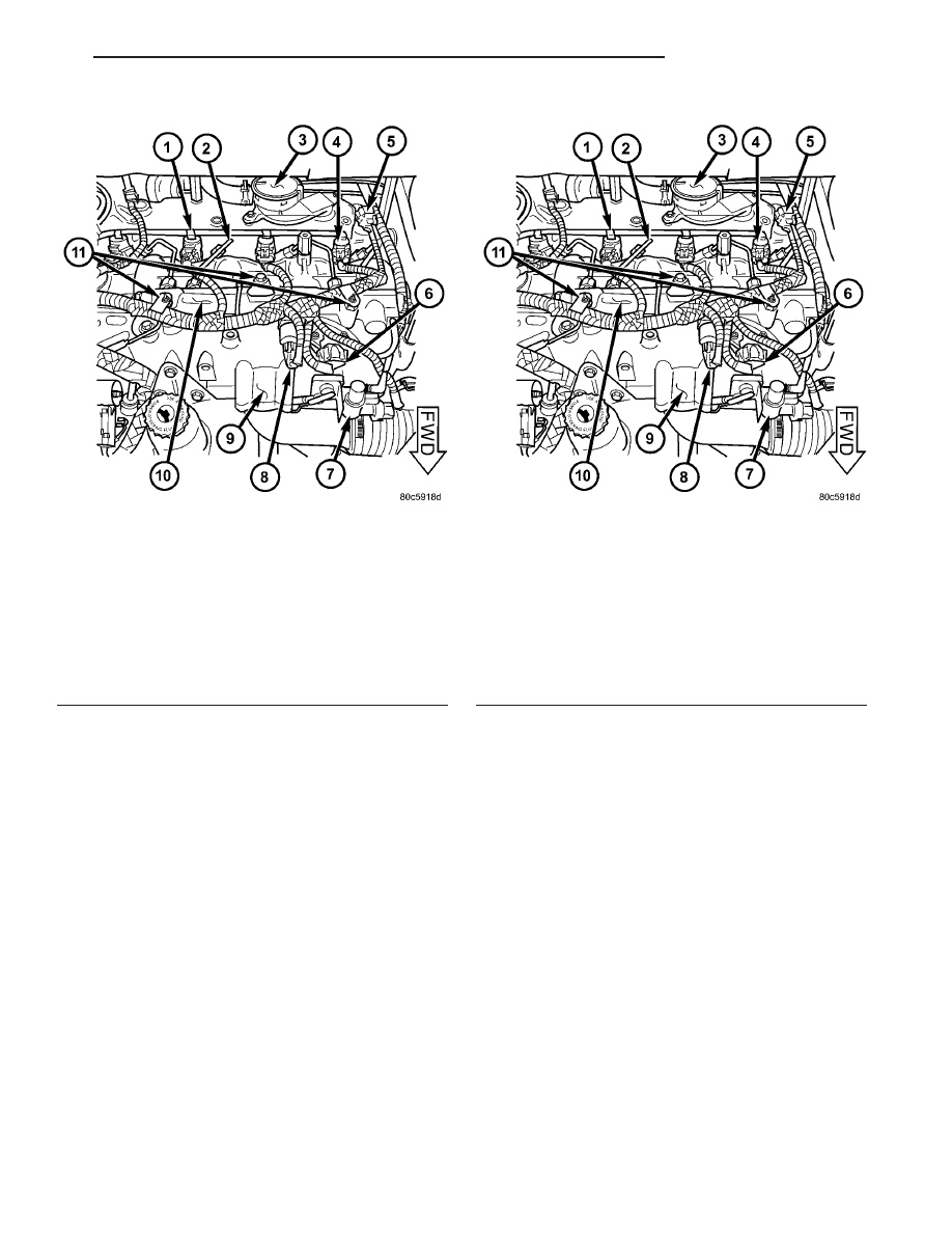
Fig. 2 FUEL RAIL COMPONENTS

1 - FUEL INJECTOR RETURN LINE
2 - FUEL INJECTOR HIGH PRESSURE LINE
3 - OIL SEPARATOR
4 - FUEL INJECTOR
5 - CAMSHAFT POSITION SENSOR
6 - BOOST PRESSURE/INTAKE AIR TEMPERATURE SENSOR
7 - EGR SOLENOID
8 - FUEL PRESSURE SENSOR
9 - CYLINDER HEAD COVER/INTAKE MANIFOLD
10 - FUEL RAIL
11 - FUEL INJECTOR WIRNING HARNESS RETAINER(S)

RG

FUEL DELIVERY

14 - 7

FUEL RAIL (Continued)

The fuel heater is installed into the filter/separator

housing above the fuel filter. Refer to Fuel Heater
Description/Operation.

REMOVAL

REMOVAL - FUEL FILTER

WARNING: NO SPARKS, OPEN FLAMES, OR SMOK-
ING. RISK OF POISONING FROM INHALING AND
SWALLOWING FUEL. RISK OF INJURY TO EYES
AND SKIN FROM CONTACT WITH FUEL. POUR
FUELS ONLY INTO SUITABLE AND APPROPRI-
ATELY MARKED CONTAINERS. WEAR PROTECTIVE
CLOTHING.

(1) Disconnect negative battery cable.
(2) Raise and support the vehicle.

(3) Clean the fuel filter/water separator housing

and dry with compressed air.

(4) Connect a drain hose to the fuel filter/water

separator drain port and place the other end in a
suitable container.

(5) Twist the fuel filter/water separator drain port-

counterclockwise and completly drain the housing.

(6) Close the draincock.
(7) Disconnect the water in fuel electrical connec-

tor.

(8) Turning counterclockwise, remove the fuel fil-

ter and bowl assembly (Fig. 3).

REMOVAL

WARNING: NO SPARKS, OPEN FLAMES OR SMOK-
ING. RISK OF POISONING FROM INHALING AND
SWALLOWING FUEL. RISK OF INJURY TO EYES
AND SKIN FROM CONTACT WITH FUEL. POUR
FUELS ONLY INTO SUITABLE AND APPROPRI-
ATELY MARKED CONTAINERS. WEAR PROTECTIVE
CLOTHING.

(1) Disconnect negative battery cable.
(2) Raise and support vehicle.
(3) Insert a suitable hose onto the fuel drain port

of the fuel filter bowl assembly, turn drain port coun-
terclockwise and drain fuel into a suitable and appro-
priately marked container (Fig. 4).

(4) Disconnect fuel supply and return lines at fuel

filter/water separator and set aside.

(5) Disconnect fuel filter/water separator electrical

connector at bracket.

(6) Remove fuel filter/water separator retaining

bracket bolts and remove assembly.

Fig. 3 FUEL FILTER/WATER SEPARATOR

1 - LIFT PUMP RETAINING BOLTS
2 - LIFT PUMP
3 - FUEL FILTER/WATER SEPARATOR HOUSING
4 - FUEL HEATER
5 - CHECK BALL
6 - O-RING
7 - FLOW DIVERTER
8 - FUEL FILTER
9 - O-RING
10 - FUEL FILTER BOWL ASSEMBLY

Fig. 4 LIFT PUMP LOCATION

14 - 8

FUEL DELIVERY

RG

FUEL FILTER / WATER SEPARATOR (Continued)

INSTALLATION

INSTALLATION - FUEL FILTER

WARNING: NO SPARKS, OPEN FLAMES, OR SMOK-
ING. RISK OF POISONING FROM INHALING AND
SWALLOWING FUEL. RISK OF INJURY TO EYES
AND SKIN FROM CONTACT WITH FUEL. POUR
FUELS ONLY INTO SUITABLE AND APPROPRI-
ATELY MARKED CONTAINERS. WEAR PROTECTIVE
CLOTHING.

(1) Inspect the new fuel filter bowl assembly

O-ring seal for proper positioning and deformities,
replace as necessary.

(2) Lubricate the O-ring seal with clean engine oil

or diesel fuel.

(3) Position the fuel filter bowl assembly to the

fuel filter/water separator (Fig. 3).

(4) Turning

clockwise,

hand

tighten

the

bowl

assembly until both mating surfaces meet, then
tighten the bowl assembly to 35N·m (26 lbs. ft.).

(5) Connect the water in fuel electrical connector.
(6) Reconnect negative battery cable.
(7) Perform the fuel system air purge procedure

(Refer to 14 - FUEL SYSTEM - STANDARD PROCE-
DURE).

(8) Start engine and inspect for fuel leaks.

INSTALLATION

WARNING: NO SPARKS, OPEN FLAMES OR SMOK-
ING. RISK OF POISONING FROM INHALING AND
SWALLOWING FUEL. RISK OF INJURY TO EYES
AND SKIN FROM CONTACT WITH FUEL. POUR
FUELS ONLY INTO SUITABLE AND APPROPRI-
ATELY MARKED CONTAINERS. WEAR PROTECTIVE
CLOTHING.

NOTE: Assure fuel filter drain port is closed.

(1) Position fuel filter/water separator bracket and

tighten retaining bolt (Fig. 4).

(2) Connect fuel filter/water separator electrical

connector.

(3) Connect fuel feed and return lines.
(4) Connect negative battery cable.
(5) Perform the fuel system air purge procedure

(Refer to 14 - FUEL SYSTEM - STANDARD PROCE-
DURE).

(6) Start engine and inspect for leaks.

FUEL INJECTION PUMP

DESCRIPTION

A radial-piston pump is used as the high pressure

pump for fuel pressure generation (Refer to 14 -
FUEL SYSTEM - WARNING) (Fig. 5).

REMOVAL

(1) Disconnect negative battery cable (Refer to 14 -

FUEL SYSTEM - WARNING).

(2) Remove engine cover (Refer to 9 - ENGINE -

REMOVAL)

(3) Remove air cleaner housing assembly.
(4) Remove power steering belt (Refer to 7 -

COOLING/ACCESSORY

DRIVE/DRIVE

BELTS

-

REMOVAL).

(5) Remove accessory drive belt (Refer to 7 -

COOLING/ACCESSORY

DRIVE/DRIVE

BELTS

-

REMOVAL).

(6) Support engine and remove right engine mount

assembly.

(7) Remove outer timing belt cover (Refer to 9 -

ENGINE/VALVE TIMING/TIMING BELT / CHAIN
COVER(S) - REMOVAL).

(8) Using special tool VM.1055, remove injection

pump sprocket retaining nut (Fig. 6).

NOTE: The use of special tool VM.1067 will allow
you to remove the injection pump without removing
the timing belt from the engine. This will allow you
to remove and install the injection pump without
altering injection pump timing.

Fig. 5 FUEL INJECTION PUMP

1 - FUEL INJECTION PUMP
2 - INJECTION PUMP PRESSURE SOLENOID

RG

FUEL DELIVERY

14 - 9

FUEL FILTER / WATER SEPARATOR (Continued)

(9) Install feet from VM.1067 in injection pump

sprocket as shown (Fig. 7).

(10) Install inner flange of special tool VM.1067 on

injection pump sprocket as shown (Fig. 8). Secure
flange to feet in injection pump sprocket with allen
bolts supplied with tool.

(11) Screw injection pump sprocket holding plate

assembly into flange of VM.1067 (Fig. 9) Using LHD
threaded bolt supplied, secure holding plate assembly
to timing belt inner cover.

(12) Remove generator (Refer to 8 - ELECTRICAL/

CHARGING/GENERATOR - REMOVAL)

(13) Disconnect fuel supply and return lines at

injection pump.

(14) Disconnect fuel pressure solenoid electrical

connector at injection pump (Fig. 10).

(15) Remove injection pump retaining nuts (Fig.

10).

(16) While holding injection pump, tighten bolt in

center of injection pump holding plate (Fig. 9).This
will push the injection pump out of the injection
pump sprocket.

INSTALLATION

(1) Loosen bolt in center of injection pump holding

plate and slide injection pump through the accessory
bracket into the injection pump sprocket (Refer to 14
- FUEL SYSTEM - WARNING).

(2) Install injection pump retaining nuts. Torque

nuts to 27.5N·m (Fig. 10).

(3) Unscrew injection pump holding plate (part of

VM.1067) from inner timing belt cover and remove
(Fig. 9).

(4) Install injection pump sprocket retaining nut to

hold sprocket in place.

(5) Remove flange and feet (both part of VM.1067)

from injection pump sprocket (Fig. 8) (Fig. 7).

(6) Using special tool VM.1055 (Fig. 6), torque

injection pump sprocket retaining nut to 88.3N·m.

(7) Connect fuel pressure solenoid electrical con-

nector (Fig. 10).

(8) Connect fuel supply and return lines at injec-

tion pump. Tighten bolts to 27.5N·m (20 lbs. ft.). (Fig.
10).

(9) Install generator (Refer to 8 - ELECTRICAL/

CHARGING/GENERATOR - INSTALLATION).

(10) Install outer timing belt cover (Refer to 9 -

ENGINE/VALVE TIMING/TIMING BELT / CHAIN
COVER(S) - INSTALLATION).

(11) Install right engine mount assembly.
(12) Install accessory drive belt (Refer to 7 -

COOLING/ACCESSORY

DRIVE/DRIVE

BELTS

-

INSTALLATION).

Fig. 6 INJECTION PUMP SPROCKET RETAINING

NUT REMOVAL/INSTALLATION

1 - IDLER PULLEY
2 - TIMING BELT
3 - VM.1055
4 - INJECTION PUMP SPROCKET

Fig. 7 VM.1067 FEET INSTALLATION

1 - OUTER TIMING BELT SEALING SURFACE
2 - TIMING BELT
3 - TIMING BELT SPROCKET
4 - FEET FOR SPECIAL TOOL VM.1067
5 - INNER TIMING BELT COVER

14 - 10

FUEL DELIVERY

RG

FUEL INJECTION PUMP (Continued)


Content   ..  1104  1105  1106  1107   ..