Chrysler Town, Dodge Caravan. Manual - part 1102


  Index      Chrysler     Chrysler TOWN & COUNTRY, VOYAGER, Dodge Caravan - service repair manual 2001-2007 year


Search            


Content   ..  1100  1101  1102  1103   ..


Chrysler Town, Dodge Caravan. Manual - part 1102


(8) Remove timing belt outer cover (Refer to 9 -

ENGINE/VALVE TIMING/TIMING BELT / CHAIN
COVER(S) - REMOVAL).

(9) Loosen and remove timing belt tensioner (Fig.

93).

INSTALLATION

CAUTION: INSPECT THE TOOTHED BELT, PULLEYS
AND BEARINGS FOR DAMAGE, SEIZURE AND
LEAKS.

NOTE: DO NOT expose the toothed belt to oil,
grease or water contamination. DO NOT clean belt,
pulleys or tensioner with solvent. DO NOT crimp

the timing belt at a sharp angle. DO NOT install belt
with levered tools forcing the belt onto the pulleys.

(1) Install timing belt tensioner and retaining bolt

(Fig. 93).

(2) Adjust timing belt tensioner (Refer to 9 -

ENGINE/VALVE

TIMING/TMNG

BELT/CHAIN

TENSIONER&PULLEY - ADJUSTMENTS).

(3) Install timing belt outer cover (Refer to 9 -

ENGINE/VALVE TIMING/TIMING BELT / CHAIN
COVER(S) - INSTALLATION).

(4) Install vibration damper (Refer to 9 - ENGINE/

ENGINE BLOCK/VIBRATION DAMPER - INSTAL-
LATION).

(5) Install accessory drive belt (Refer to 7 - COOL-

ING/ACCESSORY DRIVE/DRIVE BELTS - INSTAL-
LATION).

(6) Install power steering belt (Refer to 7 - COOL-

ING/ACCESSORY DRIVE/DRIVE BELTS - INSTAL-
LATION).

(7) Install right engine mount.
(8) Install air cleaner housing.
(9) Install engine cover (Refer to 9 - ENGINE -

INSTALLATION).

(10) Connect negative battery cable.

ADJUSTMENTS

ADJUSTMENT - TIMING BELT TENSIONER

(1) With timing belt outer cover removed and tim-

ing belt installed.

(2) Loosen timing belt tensioner (Fig. 94).
(3) Align timing belt tensioner spring stop with

tensioner as shown (Fig. 95) and torque timing belt
tensioner retaining bolt to 34.7N·m.

(4) Rotate engine 2 complete revolution and then

recheck

tensioner

alignment.

Readjust

tensioner

alignment as necessary.

TIMING BELT AND
SPROCKETS

REMOVAL

CAUTION: BEFORE REMOVING THE TIMING BELT,
THE ENGINE MUST BE PLACED AT 90° ATDC. FAIL-
URE TO DO SO COULD RESULT IN VALVE AND/OR
PISTON DAMAGE DURING REASSEMBLY. (Refer to
9 - ENGINE/VALVE TIMING - STANDARD PROCE-
DURE)

CAUTION: INSPECT THE TOOTHED BELT, PULLEYS
AND BEARINGS FOR DAMAGE, SEIZURE AND
LEAKS.

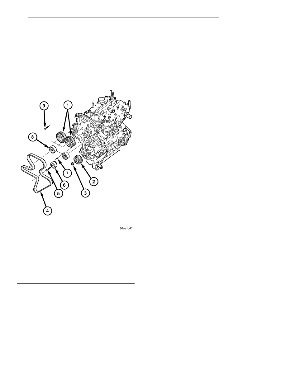
Fig. 93 TIMING BELT AND SPROCKETS

1 -CAMSHAFT SPROCKETS
2 - INJECTION PUMP SPROCKET
3 - INJECTION PUMP SPROCKET RETAINING NUT
4 - TIMING BELT
5 - TIMING BELT TENSIONER RETAINING BOLT
6 - TIMING BELT TENSIONER
7 - TENSIONER ALIGNMENT PIN
8 - IDLER PULLEY
9 - CAMSHAFT SPROCKET RETAINING BOLT

RG

ENGINE

9 - 61

TIMING BELT TENSIONER & PULLEY (Continued)

NOTE: DO NOT expose the toothed belt to oil,
grease or water contamination. DO NOT clean belt,
pulleys or tensioner with solvent. DO NOT crimp
the timing belt at a sharp angle. DO NOT install belt
with levered tools forcing the belt onto the pulleys.

(1) Disconnect negative battery cable.
(2) Remove engine cover (Refer to 9 - ENGINE -

REMOVAL).

(3) Remove air cleaner housing assembly.
(4) Support

engine

and

remove

right

engine

mount.

(5) Remove power steering belt (Refer to 7 -

COOLING/ACCESSORY

DRIVE/DRIVE

BELTS

-

REMOVAL).

(6) Remove accessory drive belt (Refer to 7 -

COOLING/ACCESSORY

DRIVE/DRIVE

BELTS

-

REMOVAL).

(7) Remove the generator.
(8) Rotate engine until #1 piston is at TDC, crank-

shaft notch on the crankshaft hub will be at 12
o’clock.

(9) Looking at the engine from the belt side, rotate

the crankshaft 90° clockwise.

(10) Install the 90° alignment pin, VM 1068 into

the crankcase threaded hole to lock crankshaft (
make sure the crankshaft will not rotate).

(11) Paint mark the crankshaft hub and the oil

pump cover. This will assist during assembly.

(12) Remove

vibration

damper

(Refer

to

9

-

ENGINE/ENGINE BLOCK/VIBRATION DAMPER -
REMOVAL).

(13) Remove timing belt outer cover (Refer to 9 -

ENGINE/VALVE TIMING/TIMING BELT / CHAIN
COVER(S) - REMOVAL).

(14) Remove the intake and exhaust camshaft

plugs from the camshaft cover to introduce the cam-
shaft timing pins.

NOTE: If the engine is already timed, install the
camshaft alignment pins (intake cam alignment pin,
VM 1052, exhaust cam alignment pin, VM 1053).

(15) Loosen timing belt tensioner and remove tim-

ing belt (Fig. 96).

(16) Using intake camshaft gear bolt, rotate intake

camshaft until the intake alignment hole lines up
with the hole in the camshaft cover. Install the
intake cam alignment pin VM 1052. Repeat the oper-
ation for the exhaust camshaft with alignment pin
VM 1053 (Fig. 96).

(17) Using VM 1055 hold the cam gears to remove

the bolts.

Fig. 94 TIMING BELT TENSIONER ADJUSTMENT

1 - TIMING BELT IDLER PULLEY
2 - ENGINE FRONT COVER
3 - CRANKSHAFT HUB
4 - TIMING BELT TENSIONER
5 - TIMING BELT

Fig. 95 TIMING BELT TENSIONER ALIGNMENT

1 - TENSIONER SPRING STOP
2 - TIMING BELT TENSIONER
3 - TIMING BELT TENSIONER
4 - TIMING BELT
5 - TIMING BELT INNER COVER

9 - 62

ENGINE

RG

TIMING BELT AND SPROCKETS (Continued)

INSTALLATION

(1) With

both

camshaft

alignment

pins

still

installed and the engine locked at 90° after TDC,
install the timing gears finger tight.

(2) Align timing mark on high pressure injection

pump sprocket with timing mark on cover (Fig. 97).

(3) Install timing belt on crankshaft hub, fix it

with VM1074, then around high pressure injection
pump, idler pulley, intake camshaft gear, exhaust
camshaft gear, idler pulley and water pump gear.

NOTE: To uniform the belt tension, slightly rotate
the intake camshaft pulley counterclockwise with
VM 1055.

(4) Adjust the timing belt tensioner (turn it clock-

wise), lining up the tensioner center notch with alu-
minum cover dowel pin. Tighten the tensioner bolt to
28N·m (20.5 lbs. ft.).(Refer to 9 - ENGINE/VALVE
TIMING/TMNG

BELT/CHAIN

TENSIONER&PULLEY - ADJUSTMENTS).

(5) Torque camshaft gear bolts to 60 N·m (44

lbs.ft.) (pre setting) holding gears with VM 1055.

(6) Remove both camshaft alignment pins from cyl-

inder head cover/intake manifold. (Refer to 9 -
ENGINE/VALVE TIMING - STANDARD PROCE-
DURE) .

(7) Torque camshaft gear bolts to 108 N·m (80

lbs.ft.) while holding gears with VM 1055.

(8) Remove 90° ATDC engine locking pin from

engine block.

CAUTION: Wait 30 minutes before rotating crank-
shaft after installing camshaft cover.

(9) Install timing belt outer cover (Refer to 9 -

ENGINE/VALVE TIMING/TIMING BELT / CHAIN
COVER(S) - INSTALLATION).

(10) Rotate crankshaft 2 times (looking at it from

the belt side)

(11) Carefully line up the painted mark on the

crankshaft hub and oil pump cover.

Fig. 96 TIMING BELT AND SPROCKETS

1 -CAMSHAFT SPROCKETS
2 - INJECTION PUMP SPROCKET
3 - INJECTION PUMP SPROCKET RETAINING NUT
4 - TIMING BELT
5 - TIMING BELT TENSIONER RETAINING BOLT
6 - TIMING BELT TENSIONER
7 - TENSIONER ALIGNMENT PIN
8 - IDLER PULLEY
9 - CAMSHAFT SPROCKET RETAINING BOLT

Fig. 97 INJECTION PUMP GEAR TIMING MARKS

1 - TIMING MARK ON COVER
2 - TIMING MARK ON INJECTION PUMP SPROCKET
3 - INJECTION PUMP SPROCKET

RG

ENGINE

9 - 63

TIMING BELT AND SPROCKETS (Continued)

CAUTION: IF THE CAMSHAFT ALIGNMENT PINS
CAN NOT BE INSTALLED, REPEAT THIS PROCE-
DURE.

(12) Check that the intake and exhaust cam align-

ment pins CAN be installed, if so remove them.

(13) Install the intake and exhaust camshaft

plugs.

(14) Install

vibration

damper

(Refer

to

9

-

ENGINE/ENGINE BLOCK/VIBRATION DAMPER -
INSTALLATION).

(15) Install the alternator.
(16) Install accessory drive belt (Refer to 7 -

COOLING/ACCESSORY

DRIVE/DRIVE

BELTS

-

INSTALLATION).

(17) Install power steering belt (Refer to 7 -

COOLING/ACCESSORY

DRIVE/DRIVE

BELTS

-

INSTALLATION).

(18) Install right engine mount.
(19) Install air cleaner housing.
(20) Install engine cover (Refer to 9 - ENGINE -

INSTALLATION).

(21) Connect negative battery cable.

9 - 64

ENGINE

RG

TIMING BELT AND SPROCKETS (Continued)


Content   ..  1100  1101  1102  1103   ..