Chrysler Town, Dodge Caravan. Manual - part 1100


  Index      Chrysler     Chrysler TOWN & COUNTRY, VOYAGER, Dodge Caravan - service repair manual 2001-2007 year


Search            


Content   ..  1098  1099  1100  1101   ..


Chrysler Town, Dodge Caravan. Manual - part 1100


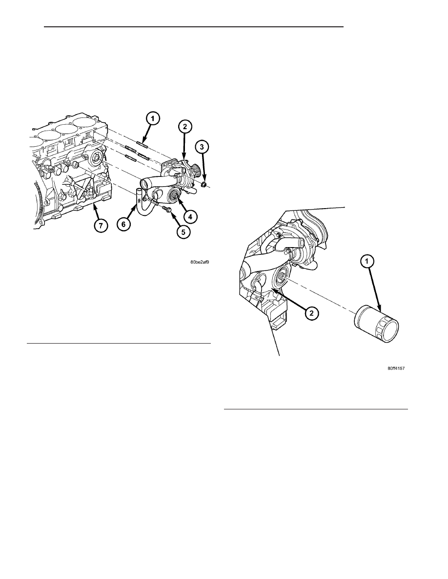
(4) Disconnect coolant hoses at cooler (Fig. 78).
(5) Remove oil cooler retaining bolt at engine block

(Fig. 78).

(6) Remove oil cooler retaining stud and remove oil

cooler from engine block (Fig. 78).

INSTALLATION

(1) Clean oil cooler and engine block sealing sur-

faces.

(2) Install oil cooler, retaining bolt, and stud (Fig.

78). Torque retaining bolt to 47.1N·m and stud to
50N·m.

(3) Connect coolant hoses at cooler (Fig. 78).
(4) Install oil filter (Refer to 9 - ENGINE/LUBRI-

CATION/OIL FILTER - INSTALLATION).

(5) Lower vehicle.
(6) Refill cooling system (Refer to 7 - COOLING/

ENGINE/COOLANT - STANDARD PROCEDURE).

(7) Start engine and check for leaks.
(8) Check and adjust oil level as necessary.

OIL FILTER

DESCRIPTION

The oil filter is a high quality, full flow, disposable

style. (Fig. 79).

REMOVAL

NOTE: Capture any residual oil spill while removing
filter and wipe any oil that comes in contact with
other components

(1) Raise vehicle on hoist.
(2) Twist oil filter counterclockwise with a suitable

oil filter wrench to remove.

INSTALLATION

(1) Lubracate oil filter seal with clean engine oil.
(2) Turning clockwise, seat the oil filter then

tighten the oil filter 1/2 turn more (Fig. 79).

(3) Lower vehicle from hoist.
(4) Start engine and check for leaks.
(5) Check and adjust oil level as necessary.

Fig. 78 WATER PUMP AND OIL COOLER

ASSEMBLIES

1 - WATER PUMP HOUSING STUDS
2 - WATER PUMP
3 - RETAINING NUTS
4 - OIL COOLER RETAINING STUD
5 - OIL COOLER TO ENGINE BLOCK RETAINING BOLT
6 - OIL COOLER COOLANT HOSE
7 - ENGINE BLOCK

Fig. 79 OIL FILTER

1 - OIL FILTER
2 - OIL COOLER

RG

ENGINE

9 - 53

OIL COOLER & LINES (Continued)

OIL JET

DESCRIPTION

There are four oil jets installed in the engine block.

These oil jets are used to cool and lubricate the pis-
ton assemblies (Fig. 80).

REMOVAL

CAUTION: Use caution when removing and install-
ing oil jets. Damage to oil jet nozzle could cause
severe engine damage.

NOTE: Remove oil jets Before removing pistons,
crankshaft or liners

(1) Disconnect negative battery cable.
(2) Raise vehicle on hoist.
(3) Remove oil pan (Refer to 9 - ENGINE/LUBRI-

CATION/OIL PAN - REMOVAL).

(4) Using special tool VM.1060 to hold oil jet.

Remove oil jet retaining bolt and remove oil jet from
engine block (Fig. 81).

INSTALLATION

CAUTION: Use caution when removing and installa-
ing oil jets. Damage to oil jet nozzle could cause
severe engine damage.

NOTE: Carefully install the oil jets After assembling
the engine liners, crankshaft and pistons.

(1) Lubricate o-ring on oil jet.
(2) Using special tool VM.1060, install oil jet in

engine block (Fig. 81).

(3) Install oil jet retaining bolt. Torque bolt to

10.8N·m.

(4) Install oil pan (Refer to 9 - ENGINE/LUBRI-

CATION/OIL PAN - INSTALLATION).

(5) Refill engine oil to proper level.
(6) Connect negative battery cable.

INTAKE MANIFOLD

DESCRIPTION

(Refer to 9 - ENGINE/CYLINDER HEAD/CYLIN-

DER HEAD COVER(S) - DESCRIPTION)

REMOVAL

(1) (Refer to 9 - ENGINE/CYLINDER HEAD/CYL-

INDER HEAD COVER(S) - REMOVAL)

INSTALLATION

(1) (Refer to 9 - ENGINE/CYLINDER HEAD/CYL-

INDER HEAD COVER(S) - INSTALLATION)

Fig. 80 OIL JET ASSEMBLY

1 - RETAINING BOLT
2 - OIL JET
3 - O-RING

Fig. 81 OIL JET REMOVAL/INSTALLATION

1 - SPECIAL TOOL VM.1060
2 - OIL JET
3 - CONNECTING ROD
4 - CRANKSHAFT

9 - 54

ENGINE

RG

VALVE TIMING

STANDARD PROCEDURE - LOCKING ENGINE
90° AFTER TDC

(1) Disconnect negative battery cable.
(2) Remove starter motor (Refer to 8 - ELECTRI-

CAL/STARTING/STARTER MOTOR - REMOVAL).

NOTE: Crankshaft hub retaining bolt is left hand
thread.

(3) Rotate engine untill notch in hub is in the fol-

lowing position (Fig. 82).

(4) Special tool VM.1068 can be install in engine

block as shown at this time (Fig. 83). This will lock
the engine at 90° after TDC.

(5) Remove front wiper unit (Refer to 8 - ELEC-

TRICAL/WIPERS/WASHERS/WIPER

MODULE

-

REMOVAL).

(6) Remove engine cover (Refer to 9 - ENGINE -

REMOVAL).

(7) Remove plug in cylinder head cover/intake

manifold and insert VM.1053 to lock exhaust cam-
shaft in position (Fig. 84).

(8) Remove generator (Refer to 8 - ELECTRICAL/

CHARGING/GENERATOR - REMOVAL).

Fig. 82 CRANKSHAFT HUB ALIGNMENT

1 - VIBRATION DAMPER/CRANKSHAFT PULLEY
2 - CRANKSHAFT HUB NOTCH
3 - VIBRATION DAMPER/CRANKSHAFT PULLEY TO
CRANKSHAFT HUB BOLTS
4 - ACCESSORY DRIVE BELT

Fig. 83 90 DEGREES AFTER TDC ALIGNMENT PIN

LOCATION

1 - ENGINE BLOCK
2 - VM.1051 TDC PIN OR VM.1068 90 DEGREES ATDC PIN
3 - FLYWHEEL

Fig. 84 EXHAUST CAMSHAFT LOCKING PIN

VM.1053

1 - EXHAUST MANIFOLD HEAT SHIELD
2 - EXHAUST CAMSHAFT LOCKING PIN VM.1053
3 - COOLANT TUBE FROM THERMOSTAT HOUSING TO UPPER
RADIATOR HOSE
4 - CYLINDER HEAD COVER/INTAKE MANIFOLD

RG

ENGINE

9 - 55

(9) Remove plug in cylinder head cover/intake

manifold and insert VM.1052 to lock intake camshaft
in position (Fig. 85).

(10) At this point the timing belt can be removed

for service.

(11) After engine service is completed and timing

belt reinstalled, remove both camshaft locking pins
from cylinder head cover/intake manifold.

(12) Install both camshaft access plugs.
(13) Remove 90° after TDC engine locking pin.
(14) Install starter motor (Refer to 8 - ELECTRI-

CAL/STARTING/STARTER MOTOR - INSTALLA-
TION).

(15) Install generator (Refer to 8 - ELECTRICAL/

CHARGING/GENERATOR - INSTALLATION).

(16) Install engine cover (Refer to 9 - ENGINE -

INSTALLATION).

(17) Install front wiper unit (Refer to 8 - ELEC-

TRICAL/WIPERS/WASHERS/WIPER

MODULE

-

INSTALLATION).

(18) Connect negative battery cable.

BALANCE SHAFT

DESCRIPTION

The 2.5L Common Rail Diesel engine is equipped

with two nodular cast iron balance shafts in a cast
aluminum carrier. The balance shaft assembly is
mounted to the engine block (Fig. 86).

OPERATION

The balance shaft is driven by the crankshaft. The

balance shafts are connected by heelical gears. The
dual-counter rotating shafts decrease second order ver-
tical shaking forces caused by component movement.

REMOVAL

(1) Disconnect negative battery cable.
(2) Raise vehicle on hoist.
(3) Before installation of the balance shaft assem-

bly, the # 1 cylinder must be brought to TDC. Using
special tool VM.1051, roll engine over by hand until
tool can be inserted into engine block locking fly-
wheel from turning.

(4) Remove oil pan (Refer to 9 - ENGINE/LUBRI-

CATION/OIL PAN - REMOVAL).

(5) Remove balance shaft assembly (Fig. 86).

Fig. 86 OIL PUMP PICKUP TUBE ASSEMBLY

1 - BALANCE SHAFT
2 - OIL JET RETAINING BOLT
3 - OIL JET
4 - ENGINE BLOCK
5 - CRANKSHAFT
6 - O- RING(S)
7 - BALANCE SHAFT RETAINING BOLTS
8 - OIL DIPSTICK TUBE RETAINER
9 - RUBBER BUSHING
10 - RETAINING BOLT

Fig. 85 INTAKE CAMSHAFT LOCKING PIN VM.1052

1 - TIMING BELT INNER COVER
2 - GLOW PLUG ELECTRICAL CONNECTOR
3 - CYLINDER HEAD COVER/INTAKE MANIFOLD
4 - FUEL RAIL
5 - INTAKE CAMSHAFT LOCKING PIN VM.1052

9 - 56

ENGINE

RG

VALVE TIMING (Continued)


Content   ..  1098  1099  1100  1101   ..