Chrysler Town, Dodge Caravan. Manual - part 1097


  Index      Chrysler     Chrysler TOWN & COUNTRY, VOYAGER, Dodge Caravan - service repair manual 2001-2007 year


Search            


Content   ..  1095  1096  1097  1098   ..


Chrysler Town, Dodge Caravan. Manual - part 1097


serrations on the cap and reference marks are
aligned (Fig. 54).

(2) Tighten connecting cap bolts to 29 N·m (21 ft.

lbs.) plus 60°.

(3) Without loosening connecting rod bolts, tighten

all bolts to 88N·m.

(4) Check and record internal diameter of crank

end of connecting rod.

CAUTION: When changing connecting rods, DO
NOT use a stamp to mark the cylinder location.
Identify the connecting rods and caps location
using a paint marker. All four must have the same
weight and the same number. Replacement con-
necting rods will only be supplied in sets of four
(Fig. 54).

Connecting rods are supplied in sets of four since

they all must be of the same weight category. Max
allowable weight difference is 5 gr.

NOTE: Lightly heat the piston in oven. Insert piston
pin in position and secure it with provided snap
rings.

After

having

coated

threads

with

Molyguard,

tighten con rod bolts to 29 N·m (21 ft. lbs.) plus 60°.

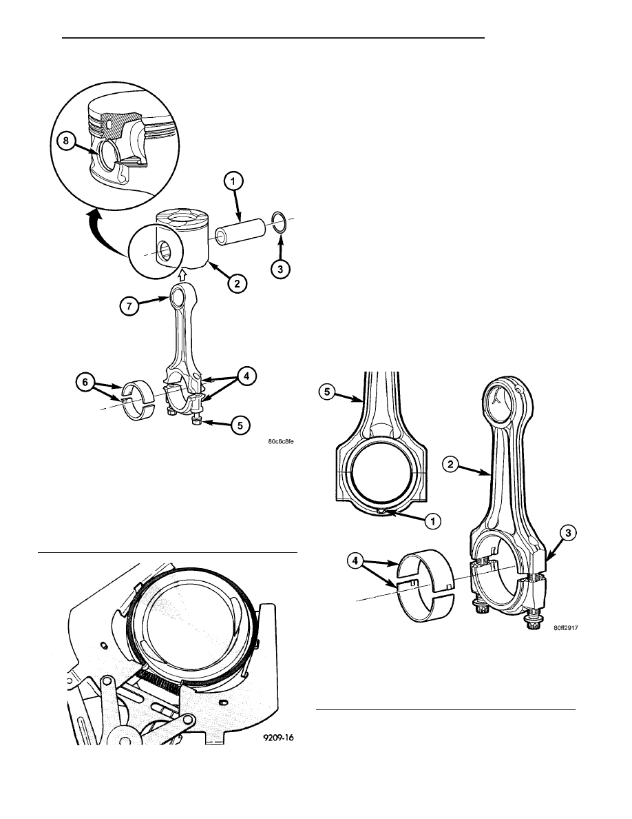
Fig. 52 PISTON AND CONNECTING ROD ASSEMBLY

1 - PISTON PIN
2 - PISTON
3 - SNAP RING
4 - PAINTED CONNECTING ROD ALIGNMENT NUMBERS
5 - CONNECTING ROD BOLT
6 - CONNECTING ROD BEARING
7 - CONNECTING ROD
8 - SNAP RING

Fig. 53 PISTON RINGS - REMOVAL/INSTALLATION

Fig. 54 CONNECTING ROD IDENTIFICATION

1 - CONNECTING ROD PAWL
2 - CONNECTING ROD
3 - PAINTED CYLINDER IDENTIFIER
4 - CONNECTING ROD BEARINGS
5 - CONNECTING ROD

RG

ENGINE

9 - 41

PISTON & CONNECTING ROD (Continued)

PISTON PINS

(1) Measure the diameter of piston pin in the cen-

ter and both ends.

(2) Piston pin diameter is 31.992 to 31.996mm

(1.259524 in to 1.259681 in.).

INSTALLATION

PISTON PIN INSTALLATION

(1) Secure connecting rod in soft jawed vice.
(2) Lubricate piston pin and piston with clean

engine oil.

(3) Position piston on connecting rod (Fig. 55).

CAUTION: Ensure arrow on piston crown and the
bearing cap numbers on the connecting rod are on
the opposite side.

(4) Install piston pin (Fig. 55).
(5) Install clips in piston to retain piston pin (Fig.

55).

(6) Remove connecting rod from vice.

PISTON RINGS - INSTALLATION

(1) Install rings on the pistons using a suitable

ring expander (Fig. 56).

(2) Top compression ring is tapered and chromium

plated. The second ring is of the scraper type and
must be installed with scraping edge facing bottom of
the piston. The third is an oil control ring. Ring gaps
must be positioned, before inserting piston into the
liners, as follows.

(3) Top ring gap must be positioned at the #3 posi-

tion (looking at the piston crown from above) (Fig.
57).

(4) Second piston ring gap should be positioned at

the #1 position (Fig. 57).

(5) Oil control ring gap should be positioned at the

#2 position (Fig. 57).

(6) When assembling pistons check that compo-

nents are installed in the same position as before dis-
assembly, determined by the numbers stamped on
the crown of individual pistons. Engine cylinders are
numbered starting from gear train end of the engine.
Face arrow on top of piston toward front of
engine
. Therefore, the numbers stamped on connect-
ing rod big end should face toward the injection
pump side of engine. To insert piston into cylinder
use a ring compressor (VM.1065) as shown in (Fig.
58).

INSTALLATION

(1) Before installing pistons, and connecting rod

assemblies into the bore, be sure that compression
ring gaps are staggered so that neither is in line with
oil ring rail gap (Fig. 57).

Fig. 55 PISTON AND CONNECTING ROD ASSEMBLY

1 - PISTON PIN
2 - PISTON
3 - SNAP RING
4 - PAINTED CONNECTING ROD ALIGNMENT NUMBERS
5 - CONNECTING ROD BOLT
6 - CONNECTING ROD BEARING
7 - CONNECTING ROD
8 - SNAP RING

Fig. 56 PISTON RINGS-INSTALLATION

9 - 42

ENGINE

RG

PISTON & CONNECTING ROD (Continued)

(2) Before installing the ring compressor, make

sure the oil ring expander ends are butted together.

(3) Immerse the piston head and rings in clean

engine oil, slide the ring compressor, over the piston
and tighten (Fig. 58). Ensure position of rings
does not change during this operation
.

NOTE: Be sure arrow on top of piston faces
towards front of engine and the connecting rod
pawl faces the rear (flywheel) side of the engine.

NOTE: Be careful not to nick crankshaft journals.

(4) Rotate crankshaft so that the connecting rod

journal is on the center of the cylinder bore. Insert
rod and piston into cylinder bore and guide rod over
the crankshaft journal.

(5) Tap the piston down in cylinder bore, using a

hammer handle. At the same time, guide connecting
rod into position on connecting rod journal.

NOTE: Connecting rod bolts must be replaced when
disassembled. DO NOT lubracate new connecting
rod bolts as they are already coated.

(6) Install connecting rod caps (Fig. 59). Install rod

bolts and tighten each bolt to 10N·m (89 lbs. in..).
Tighten each bolt again to 30N·m (22 lbs. ft.) plus
40°. Then torque to 88N·m (65 ft.lb).

(7) Install cylinder head (Refer to 9 - ENGINE/

CYLINDER HEAD - INSTALLATION).

(8) Install balance shaft assembly (Refer to 9 -

ENGINE/VALVE

TIMING/BALANCE

SHAFT

-

INSTALLATION).

(9) Install oil pump pickup tube (Refer to 9 -

ENGINE/LUBRICATION/OIL PUMP - INSTALLA-
TION).

(10) Install oil pan (Refer to 9 - ENGINE/LUBRI-

CATION/OIL PAN - INSTALLATION).

(11) Connect negative battery cable.

Fig. 57 PISTON RING GAP LOCATION

1 - SECOND COMPRESSION RING GAP POSITION
2 - OIL CONTROL RING GAP POSITION
3 - TOP COMPRESSION RING GAP POSITION

Fig. 58 PISTON INSTALLATION USING VM.1065

PISTON
PISTON RING COMPRESSOR VM.1065
ENGINE BLOCK

Fig. 59 PISTON AND CONNECTING ROD

INSTALLATION

1 - PISTON AND CONNECTING ROD ASSEMBLY
2 - PAINTED CYLINDER IDENTIFIER
3 - CONNECTING ROD BOLT
4 - PAINTED CYLINDER IDENTIFIER

RG

ENGINE

9 - 43

PISTON & CONNECTING ROD (Continued)

CRANKSHAFT OIL SEAL -
FRONT

REMOVAL

(1) Disconnect negative battery cable.
(2) Remove air cleaner housing.
(3) Support engine and remove right engine mount

(Refer to 9 - ENGINE/ENGINE MOUNTING/RIGHT
MOUNT - REMOVAL).

(4) Remove power steering belt (Refer to 7 -

COOLING/ACCESSORY

DRIVE/DRIVE

BELTS

-

REMOVAL).

(5) Remove accessory drive belt (Refer to 7 -

COOLING/ACCESSORY

DRIVE/DRIVE

BELTS

-

REMOVAL).

(6) Remove

vibration

damper/crankshaft

pulley

(Refer to 9 - ENGINE/ENGINE BLOCK/VIBRATION
DAMPER - REMOVAL).

(7) Remove outer timing belt cover (Refer to 9 -

ENGINE/VALVE TIMING/TIMING BELT / CHAIN
COVER(S) - REMOVAL).

(8) Remove timing belt (Refer to 9 - ENGINE/

VALVE

TIMING/TIMING

BELT/CHAIN

AND

SPROCKETS - REMOVAL).

(9) Remove timing belt inner cover (Refer to 9 -

ENGINE/VALVE TIMING/TIMING BELT / CHAIN
COVER(S) - REMOVAL).

NOTE: Crankshaft hub retaining bolt has LHD
thread.

(10) Remove crankshaft hub.
(11) Remove front engine cover (Fig. 60) (Refer to

9 - ENGINE/ENGINE BLOCK/ENGINE COVER -
REMOVAL) .

(12) With cover on work bench, pry out old seal.

INSTALLATION

CAUTION: Do Not use a hammer to install the
crankshaft oil seal.

NOTE: To prevent potential oil leaks, DO NOT touch
the front crankshaft inner seal. Always handle the
seal from the outer diameter.

(1) Clean engine block and front engine cover seal-

ing surfaces.

(2) Install crankshaft oil seal on VM.1061 (Fig.

61).

(3) Place sleeve for VM.1061 on press bench as

shown (Fig. 61).

(4) Press the new seal into front engine cover.

Fig. 60 ENGINE COVER - FRONT

1 - CRANKSHAFT HUB RETAINING BOLT
2 - FRONT ENGINE COVER RETAINING BOLTS
3 - ENGINE BLOCK
4 - FRONT ENGINE COVER ALIGNMENT DOWELS
5 - FRONT ENGINE COVER
6 - CRANKSHAFT HUB

Fig. 61 VM.1061 PLACEMENT

1 - VM.1061
2 - FRONT ENGINE COVER
3 - PRESS BENCH
4 - SLEEVE FROM VM.1061

9 - 44

ENGINE

RG


Content   ..  1095  1096  1097  1098   ..