Chrysler Town, Dodge Caravan. Manual - part 1096


  Index      Chrysler     Chrysler TOWN & COUNTRY, VOYAGER, Dodge Caravan - service repair manual 2001-2007 year


Search            


Content   ..  1094  1095  1096  1097   ..


Chrysler Town, Dodge Caravan. Manual - part 1096


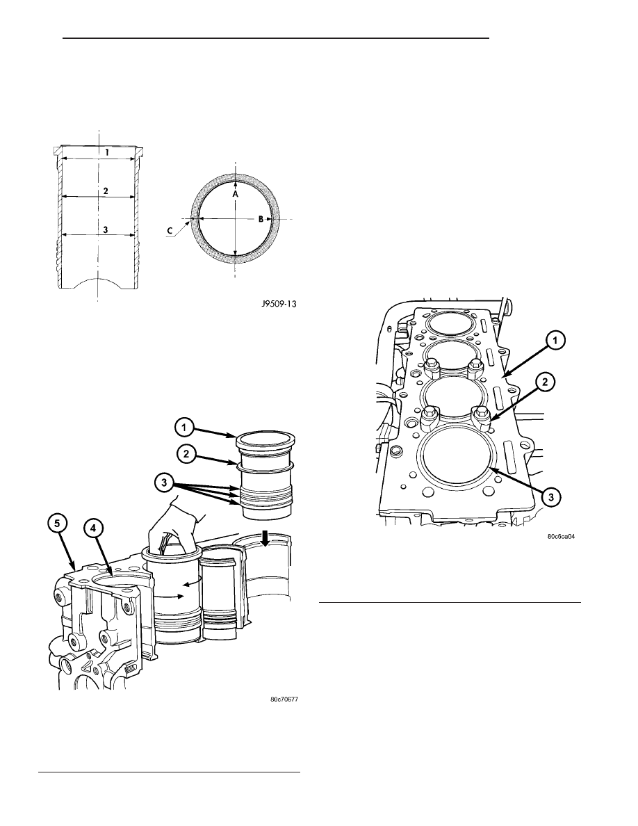
Measure the cylinder bore at three levels in direc-

tions A and B (Fig. 43). Top measurement should be
10 mm (3/8 in.) down and bottom measurement
should be 10 mm (3/8 in.) up from the bottom bore.

INSTALLATION

(1) Carefully clean liner and engine block, and

degrease the engine block where it comes into contact
with the liners. Install the liners in the engine block
as shown, rotating them back and forth by 45° in
order to guarantee correct positioning (Fig. 44).

(2) Measure the liner recess relative to block deck

with a dial indicator mounted on a special tool
VM-1010 A. All the measurements must be taken
on high pressure pump side of engine block. 
.
Zero dial gauge on block deck.

(3) Move dial gauge to cylinder liner record read-

ing on dial gauge.

(4) Remove liner and special tool.
(5) Then select the correct shim thickness to give

proper protrusion (0.01 - 0.06 mm).

(6) Fit the shim and the O-rings onto the liner.
(7) Lubricate the lower liner location in the block.
(8) Fit the liners in the crankcase making sure

that the shim is positioned correctly in the seat. Lock
the liners in position using special tool (VM.1076)
and bolts (Fig. 45).

(9) Recheck the liner protrusion. It should be 0.00

- 0.05 mm.

(10) Reassemble engine.
(11) Install engine in vehicle.

Fig. 43 LINER INSPECTION

Fig. 44 LINER INSTALLATION

1 - CYLINDER LINER
2 - SHIMS
3 - O-RINGS
4 - BLOCK LEDGE
5 - ENGINE BLOCK

Fig. 45 LINER CLAMP LOCATION

1 - ENGINE BLOCK
2 - LINER RETAINER VM.1076
3 - CYLINDER LINER

RG

ENGINE

9 - 37

CYLINDER LINERS (Continued)

INTERNAL VACUUM PUMP

DESCRIPTION

The diesel engine uses a internal vacuum pump.

This vacuum pump is mounted in the front of the
engine block under the engine front cover (Fig. 46).
The vacuum pump is driven by a sprocket on the
crankshaft.

REMOVAL

(1) Disconnect negative battery cable.
(2) Remove air cleaner housing.
(3) Remove power steering belt (Refer to 7 -

COOLING/ACCESSORY

DRIVE/DRIVE

BELTS

-

REMOVAL).

(4) Remove accessory drive belt (Refer to 7 -

COOLING/ACCESSORY

DRIVE/DRIVE

BELTS

-

REMOVAL).

(5) Support engine and remove right engine mount

(Refer to 9 - ENGINE/ENGINE MOUNTING/RIGHT
MOUNT - REMOVAL).

(6) Remove

vibration

damper/crankshaft

pulley

(Refer to 9 - ENGINE/ENGINE BLOCK/VIBRATION
DAMPER - REMOVAL).

(7) Remove outer timing belt cover (Refer to 9 -

ENGINE/VALVE TIMING/TIMING BELT / CHAIN
COVER(S) - REMOVAL).

(8) Remove timing belt (Refer to 9 - ENGINE/

VALVE

TIMING/TIMING

BELT/CHAIN

AND

SPROCKETS - REMOVAL).

(9) Remove timing belt inner cover (Refer to 9 -

ENGINE/VALVE TIMING/TIMING BELT / CHAIN
COVER(S) - REMOVAL).

NOTE: Crankshaft hub has LHD thread.

(10) Remove crankshaft hub.
(11) Remove front engine cover (Refer to 9 -

ENGINE/ENGINE

BLOCK/ENGINE

COVER

-

REMOVAL).

(12) Remove crankshaft sprocket (Fig. 47).
(13) Remove vacuum pump (Fig. 47).

INSTALLATION

NOTE: Verify the 3 blades on the vacuum pump are
in place and correctly assembled. The tapered edge
should be on the outer side. Make sure the pump
rotates before installation.

(1) Lubricate vacuum pump blades and install in

vacuum pump body as shown (Fig. 48).

(2) Install vacuum pump in engine block (Fig. 47).

Torque bolts to 10.8N·m.

(3) Install crankshaft sprocket (Fig. 47). Torque

bolts to 10.8N·m.

(4) Install

front

engine

cover

(Refer

to

9

-

ENGINE/ENGINE

BLOCK/ENGINE

COVER

-

INSTALLATION).

(5) Install front crankshaft hub. Torque bolt to

304N·m.

(6) Install timing belt inner cover (Refer to 9 -

ENGINE/VALVE TIMING/TIMING BELT / CHAIN
COVER(S) - INSTALLATION).

(7) Install timing belt (Refer to 9 - ENGINE/

VALVE

TIMING/TIMING

BELT/CHAIN

AND

SPROCKETS - INSTALLATION).

Fig. 46 VACUUM PUMP

Fig. 47 OIL PUMP AND VACUUM PUMP

1 - VACUUM PUMP
2 - CRANKSHAFT SPROCKET
3 - OIL PUMP
4 - ENGINE BLOCK
5 - CRANKSHAFT

9 - 38

ENGINE

RG

(8) Install timing belt outer cover (Refer to 9 -

ENGINE/VALVE TIMING/TIMING BELT / CHAIN
COVER(S) - INSTALLATION).

(9) Install vibration damper/crankshaft pulley.
(10) Install right engine mount (Refer to 9 -

ENGINE/ENGINE MOUNTING/RIGHT MOUNT -
INSTALLATION).

(11) Install accessory drive belt (Refer to 7 -

COOLING/ACCESSORY

DRIVE/DRIVE

BELTS

-

INSTALLATION).

(12) Install power steering belt (Refer to 7 -

COOLING/ACCESSORY

DRIVE/DRIVE

BELTS

-

INSTALLATION).

(13) Install air cleaner housing.
(14) Connect negative battery cable.

PISTON & CONNECTING ROD

DESCRIPTION

The pistons are of a free floating design. Oil jets in

the engine block lubricate and cool the piston and pin
assembly. The connecting rods have a pressed in
place wrist pin bushing which is lubricated by the oil
jets (Fig. 49).

STANDARD PROCEDURE - PISTON RING
FITTING

(1) Wipe cylinder bore clean. Insert ring and push

down with piston to ensure it is square in bore. The
ring gap measurement must be made with the ring
positioning at least 12 mm (0.50 in.) from bottom of
cylinder bore (Fig. 50). Check gap with feeler gauge.

Top compression ring gap .30 to .45mm (.0118 to
.0177 in.). Second compression ring gap .30 to .45mm
(.0118 to .0177 in.). Oil control ring gap .25 to .50mm
(.0098 to .0196 in.).

(2) If ring gaps exceed dimension given, new rings

or cylinder liners must be fitted. Keep piston rings in
piston sets.

(3) Check piston ring to groove clearance (Fig. 51).

Top compression ring gap .080 to .130mm (.0031 to
.0051 in.). Second compression ring gap .070 to
.110mm (.0027 to .0043 in.). Oil control ring gap .040
to .080mm (.0015 to .0031 in.).

REMOVAL

(1) Disconnect negative battery cable.
(2) Remove cylinder head (Refer to 9 - ENGINE/

CYLINDER HEAD - REMOVAL).

Fig. 48 VACUUM PUMP COMPONENTS

1 - VACUUM PUMP BODY
2 - VACUUM PUMP BLADE TAPERED EDGE
3 - VACUUM PUMP BLADE

Fig. 49 PISTON AND CONNECTING ROD ASSEMBLY

1 - PISTON PIN
2 - PISTON
3 - SNAP RING
4 - PAINTED CONNECTING ROD ALIGNMENT NUMBERS
5 - CONNECTING ROD BOLT
6 - CONNECTING ROD BEARING
7 - CONNECTING ROD
8 - SNAP RING

RG

ENGINE

9 - 39

INTERNAL VACUUM PUMP (Continued)

(3) Raise vehicle on hoist.
(4) Remove oil pan (Refer to 9 - ENGINE/LUBRI-

CATION/OIL PAN - REMOVAL).

(5) Remove oil pump pickup tube.(Refer to 9 -

ENGINE/LUBRICATION/OIL PUMP - REMOVAL)

(6) Remove balance shaft assembly (Refer to 9 -

ENGINE/VALVE

TIMING/BALANCE

SHAFT

-

REMOVAL).

(7) Remove top ridge of cylinder bores with a ridge

reamer before removing pistons from cylinder block.
Be sure to keep top of pistons covered during
this operation.

(8) Piston and connecting rods must be removed

from top of cylinder block. Rotate crankshaft so that
each connecting rod is centered in cylinder bore.

NOTE: Be careful not to nick or scratch crankshaft
journals, connecting rod cap can be separated by
tapping with a plastic hammer on a clean surface.

(9) After removal, install bearing cap on the mat-

ing rod and mark piston and connecting rod with
painted matching cylinder number when removed
from engine block.

PISTON PIN - REMOVAL

(1) Secure connecting rods in a soft jawed vice.
(2) Remove 2 snap rings securing piston pin (Fig.

52).

(3) Push piston pin out of piston and connecting

rod (Fig. 52).

PISTON RING - REMOVAL

(1) ID mark on face of top and second piston rings

must point toward piston crown.

(2) Using a suitable ring expander, remove top and

second piston rings (Fig. 53).

(3) Remove upper oil ring side rail, lower oil ring

side rail and then the oil expander from piston.

(4) Carefully clean carbon from piston crowns,

skirts and ring grooves ensuring the 4 oil holes in
the oil control ring groove are clear.

INSPECTION

PISTONS

(1) Piston

Diameter:

Size:

91.912-91.928mm

(3.6185-3.6192 in.) Maximum wear limit .05mm
(.0019 in.).

(2) Check piston pin bores in piston for roundness.

Make 3 checks at 120° intervals. Maximum out of
roundness .05mm (.0019in.).

(3) The

piston

diameter

should

be

measured

approximately 15 mm (.590 in.) up from the base.

(4) Skirt wear should not exceed 0.1 mm (.00039

in.).

(5) The clearance between the cylinder liner and

piston

should

not

exceed

0.065-0.083

mm

(.0025-.0032 in.).

CONNECTING RODS

CAUTION: When assembling the connecting rod, be
sure that the pawl on each of the connecting rod
caps is facing the rear (fly wheel) side of the engine
(Fig. 54).

(1) Assemble bearing shells and bearing caps to

their respective connecting rods ensuring that the

Fig. 50 RING END GAP MEASUREMENT

1 - FEELER GAUGE

Fig. 51 PISTON RING TO GROOVE CLEARANCE

9 - 40

ENGINE

RG

PISTON & CONNECTING ROD (Continued)


Content   ..  1094  1095  1096  1097   ..