Chrysler Town, Dodge Caravan. Manual - part 1092


  Index      Chrysler     Chrysler TOWN & COUNTRY, VOYAGER, Dodge Caravan - service repair manual 2001-2007 year


Search            


Content   ..  1090  1091  1092  1093   ..


Chrysler Town, Dodge Caravan. Manual - part 1092


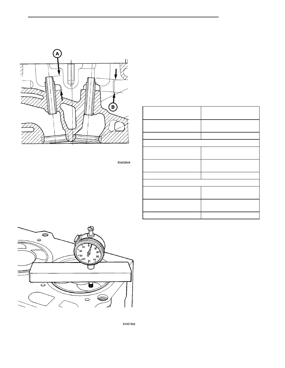
STANDARD PROCEDURE - MEASURING
PISTON PROTRUSION

(1) Use special tool VM.1010 with dial indicator

special tool VM.1013 (Fig. 14).

(2) Bring the piston of cylinder no. 1 exactly to top

dead center.

(3) Zero the dial indicator on the cylinder block

mating surface.

(4) Setup the dial indicator on the piston crown

(above the center of the piston pin) 5mm (1/8 in.)
from the edge of the piston and note the measure-
ment.

(5) Repeat the procedure with the rest of the cyl-

inders.

(6) Establish the thickness of the steel gasket by

averaging the four piston potrusion readings.

Measure Dimension
(mm)

0.49-0.60

Cylinder Head Gasket
Thickness (mm)

1.32
No Holes or Notches

Piston Clearance (mm)

0.72-0.83

Measure Dimension
(mm)

0.61-0.70

Cylinder Head Gasket
Thickness (mm)

1.42
1 Hole or Notch

Piston Clearance (mm)

0.72-0.81

Measure Dimension
(mm)

0.71-0.83

Cylinder Head Gasket
Thickness (mm)

1.52
2 Holes or Notches

Piston Clearance (mm)

0.69-0.81

REMOVAL

(1) Disconnect negative battery cable.
(2) Remove front wiper unit (Refer to 8 - ELEC-

TRICAL/WIPERS/WASHERS/WIPER

MODULE

-

REMOVAL).

(3) Remove engine cover (Refer to 9 - ENGINE -

REMOVAL).

(4) Drain cooling system (Refer to 7 - COOLING/

ENGINE/COOLANT - STANDARD PROCEDURE).

(5) Remove power steering belt (Refer to 7 -

COOLING/ACCESSORY

DRIVE/DRIVE

BELTS

-

REMOVAL).

(6) Remove accessory drive belt (Refer to 7 -

COOLING/ACCESSORY

DRIVE/DRIVE

BELTS

-

REMOVAL).

(7) Remove generator (Refer to 8 - ELECTRICAL/

CHARGING/GENERATOR - REMOVAL).

(8) Support engine and remove right engine mount

(Refer to 9 - ENGINE/ENGINE MOUNTING/RIGHT
MOUNT - REMOVAL).

Fig. 13 VALVE GUIDE HEIGHT

Fig. 14 PISTON PROTRUSION

RG

ENGINE

9 - 21

CYLINDER HEAD (Continued)

CAUTION: Before removing the cylinder head cover/
intake manifold or timing belt the engine must put
at 90° after TDC. Failure to do so could result in
valve and/or piston damage during reassembly.
(Refer to 9 - ENGINE/VALVE TIMING - STANDARD
PROCEDURE)

(9) Remove timing belt outer cover (Refer to 9 -

ENGINE/VALVE TIMING/TIMING BELT / CHAIN
COVER(S) - REMOVAL).

(10) Remove timing belt (Refer to 9 - ENGINE/

VALVE

TIMING/TIMING

BELT/CHAIN

AND

SPROCKETS - REMOVAL).

(11) Remove timing belt inner cover (Refer to 9 -

ENGINE/VALVE TIMING/TIMING BELT / CHAIN
COVER(S) - REMOVAL).

(12) Remove cylinder head cover/intake manifold

(Fig. 15)(Refer to 9 - ENGINE/CYLINDER HEAD/
CYLINDER HEAD COVER(S) - REMOVAL).

(13) Remove rocker arm and lifter assemblies from

cylinder head.

(14) Remove cylinder head cover/intake manifold

gasket from cylinder head.

(15) Disconnect glow plug and engine coolant tem-

perture electrical connectors.

(16) Remove coolant recovery pressure container

(Refer to 7 - COOLING/ENGINE/COOLANT RECOV-
ERY PRESS CONTAINER - REMOVAL).

(17) Remove thermostat housing to upper radiator

hose pipe (Fig. 16).

(18) Remove turbocharger outlet to charge air

cooler pipe (Fig. 16).

Fig. 15 CYLINDER HEAD COVER/INTAKE

MANIFOLD ASSEMBLY

1 - CYLINDER HEAD COVER/INTAKE MANIFOLD BOLTS(LONG)
2 - CYLINDER HEAD COVER/INTAKE MANIFOLD
3 - CYLINDER HEAD
4 - CYLINDER HEAD COVER/INTAKE MANIFOLD GASKET
5 - CYLINDER HEAD COVER/INTAKE MANIFOLD BOLTS(SHORT)

Fig. 16 TURBOCHARGER AND COOLANT PIPES

1 - TURBOCHARGER OUTLET PIPE RETAINING BOLT
2 - TURBOCHARGER OUTLET PIPE
3 - ADAPTOR HOSE
4 - HOSE CLAMPS
5 - TURBOCHARGER INLET PIPE RETAINING BOLT
6 - TURBOCHARGER INLET PIPE
7 - ADAPTOR HOSE
8 - HOSE CLAMPS
9 - EGR VALVE TO INTAKE AIR INLET PIPE
10 - CLAMP
11 - THERMOSTAT HOUSING TO UPPER RADIATOR HOSE PIPE

9 - 22

ENGINE

RG

CYLINDER HEAD (Continued)

(19) Remove exhaust manifold heat shield (Fig.

17).

(20) Remove exhaust manifold retaining nuts (Fig.

17).

(21) Slide exhaust manifold and turbocharger off of

exhaust manifold studs (Fig. 17).

(22) Remove cylinder head bolts.
(23) Remove cylinder head assembly from engine

block (Fig. 18).

CLEANING

Thoroughly clean the engine cylinder head and cyl-

inder block mating surfaces. Clean the intake and
exhaust manifold and engine cylinder head mating
surfaces. Remove all gasket material and carbon.

Check to ensure that no coolant or foreign material

has fallen into the tappet bore area.

Remove the carbon deposits from the combustion

chambers and top of the pistons.

INSPECTION

Use a straightedge and feeler gauge to check the

flatness of the engine cylinder head and block mating
surfaces.

The minimum cylinder head thickness is 89.95mm

(3.541 in.).

INSTALLATION

CAUTION: Piston protrusion must be measured to
determine cylinder head gasket thickness if one or
more cylinder liners have been replaced (Refer to 9
- ENGINE/CYLINDER HEAD - STANDARD PROCE-
DURE).

NOTE: If cylinder liner(s) have not been removed,
the same thickness head gasket that was removed
can be used.

(1) Clean and inspect gasket mating surfaces.

Fig. 17 EXHAUST MANIFOLD AND

TURBOCHARGER

1 - TURBOCHARGER OIL SUPPLY BANJO BOLT
2 - COPPER WASHER
3 - EXHAUST MANIFOLD GASKET
4 - COPPER WASHER
5 - TURBOCHARGER
6 - HEAT SHIELD RETAINING BOLT
7 - ENGINE LIFT HOOK
8 - LIFT HOOK RETAINING BOLT
9 - EXHAUST MANIFOLD RETAINING NUT
10 - TURBOCHARGER RETURN HOSE
11 - EXHAUST MANIFOLD STUD

Fig. 18 CYLINDER HEAD ASSEMBLY

1 - VALVE SPRING
2 - CYLINDER HEAD BOLT
3 - GLOW PLUG
4 - COOLANT TEMPERATURE SENSOR
5 - CYLINDER HEAD ALIGNMENT DOWEL
6 - CYLINDER BLOCK
7 - CYLINDER LINER
8 - ENGINE BLOCK DECK
9 - CYLINDER HEAD GASKET
10 - CYLINDER HEAD
11 - ROCKER ARM AND LIFTER ASSEMBLY

RG

ENGINE

9 - 23

CYLINDER HEAD (Continued)

(2) Position correct head gasket on engine block.
(3) Place cylinder head on engine block (Fig. 18).

CAUTION: New cylinder head bolts must be used.

(4) Tighten cylinder head bolts following procedure

below.

Cylinder Head Bolt Torquing Procedure

(1) Lubricate cylinder head bolts with engine oil.
(2) Torque bolts to 30N·m in numerical starting

with bolt #1 (Fig. 19).

(3) Tighten all bolts an additional 75°, starting

with bolt #4 then 5-6-7-8-9-10-1-2-3 (Fig. 19).

(4) Tighten all bolts an additional 50° in numerical

order starting with bolt #11 then 12-13-14-15-16-
17-18 (Fig. 19).

(5) Without loosening any bolts tighten all bolts an

additional 75° in the following seguence: 4-5-6-7-8-9-
10-1-2-3-11-12-13-14-15-16-17-18.

(5) Slide exhaust manifold and turbocharger on

exhaust manifold studs (Fig. 17).

(6) Install exhaust manifold retaining nuts. Torque

nuts to 32.4N·m.

(7) Install exhaust manifold heat shield (Fig. 17).

Torque bolts to 27.5N·m.

(8) Install turbocharger outlet to charge air cooler

pipe (Fig. 17).

(9) Install thermostat housing to upper radiator

hose pipe (Fig. 16). Install retaining bolt and torque
to 47.1N·m.

(10) Install coolant recovery pressure container

(Refer to 7 - COOLING/ENGINE/COOLANT RECOV-
ERY PRESS CONTAINER - INSTALLATION).

(11) Connect glow plug and coolant temperature

sensor electrical connectors.

(12) Install new cylinder head cover/intake mani-

fold gasket.

(13) Install rocker arm and lifter assemblies.Be

sure to put rocker arm and lifter assemblies in
same location as removed.

(14) Install cylinder head cover/intake manifold

(Fig. 15)(Refer to 9 - ENGINE/CYLINDER HEAD/
CYLINDER HEAD COVER(S) - INSTALLATION).

(15) Install timing belt inner cover (Refer to 9 -

ENGINE/VALVE TIMING/TIMING BELT / CHAIN
COVER(S) - INSTALLATION).

(16) Install timing belt (Refer to 9 - ENGINE/

VALVE

TIMING/TIMING

BELT/CHAIN

AND

SPROCKETS - INSTALLATION).

(17) Install timing belt outer cover (Refer to 9 -

ENGINE/VALVE TIMING/TIMING BELT / CHAIN
COVER(S) - INSTALLATION).

(18) Remove crankshaft and both camshaft

locking pins at this time (Refer to 9 - ENGINE/
VALVE TIMING - STANDARD PROCEDURE) .

(19) Install generator (Refer to 8 - ELECTRICAL/

CHARGING/GENERATOR - INSTALLATION).

(20) Install accessory drive belt (Refer to 7 -

COOLING/ACCESSORY

DRIVE/DRIVE

BELTS

-

INSTALLATION).

(21) Install power steering belt (Refer to 7 -

COOLING/ACCESSORY

DRIVE/DRIVE

BELTS

-

INSTALLATION).

(22) Install right engine mount (Refer to 9 -

ENGINE/ENGINE MOUNTING/RIGHT MOUNT -
INSTALLATION).

(23) Install air cleaner housing assembly.
(24) Refill cooling system (Refer to 7 - COOLING/

ENGINE/COOLANT - STANDARD PROCEDURE).

(25) Install engine cover (Refer to 9 - ENGINE -

INSTALLATION).

(26) Install front wiper unit (Refer to 8 - ELEC-

TRICAL/WIPERS/WASHERS/WIPER

MODULE

-

INSTALLATION).

(27) Connect negative battery cable.

Fig. 19 CYLINDER HEAD TORQUE SEQUENCE

9 - 24

ENGINE

RG

CYLINDER HEAD (Continued)


Content   ..  1090  1091  1092  1093   ..