Chrysler Town, Dodge Caravan. Manual - part 1080


  Index      Chrysler     Chrysler TOWN & COUNTRY, VOYAGER, Dodge Caravan - service repair manual 2001-2007 year


Search            


Content   ..  1078  1079  1080  1081   ..


Chrysler Town, Dodge Caravan. Manual - part 1080


INSTALLATION

INSTALLATION-ACCESSORY DRIVE BELT

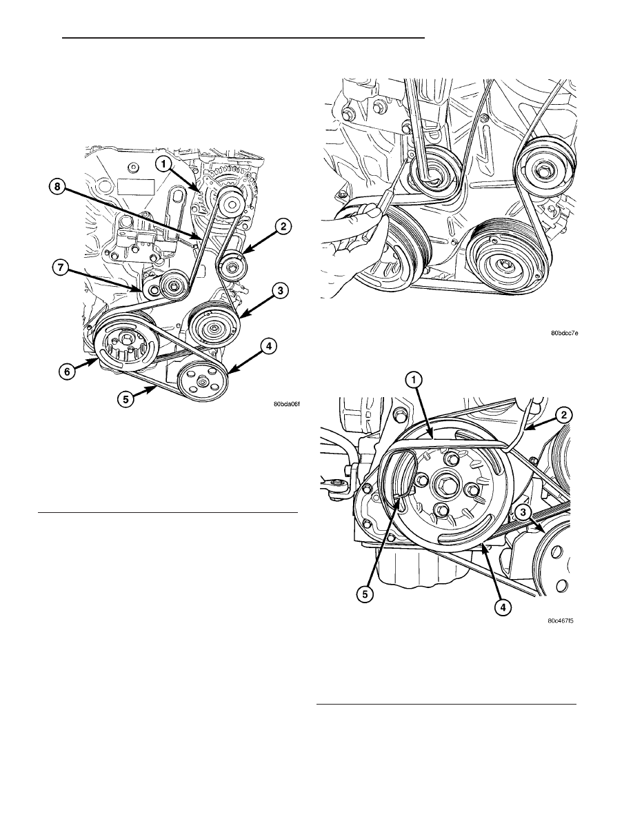
(1) Install the accessory drive belt in proper popsi-

tion (Fig. 8).

(2) Unlock belt tensioner by removing punch and

apply tension to accessory drive belt (Fig. 9).

(3) Install the power steering belt (Refer to 7 -

COOLING/ACCESSORY

DRIVE/DRIVE

BELTS

-

INSTALLATION).

INSTALLATION-POWER STEERING BELT

(1) Install power steering belt installation tool

(Fig. 10).

(2) Install power steering belt on crankshaft and

rotate

crankshaft

clockwise

until

belt

is

fully

installed on crankshaft (Fig. 10).

(3) Remove installation tool from crankshaft.
(4) Install right front fender inner splash shield.
(5) Lower vehicle from hoist.

Fig. 8 ACCESSORY DRIVE BELT ROUTING

1 - GENERATOR
2 - IDLER PULLEY
3 - A/C COMPRESSOR CLUTCH
4 - POWER STEERING PUMP PULLEY
5 - POWER STEERING BELT
6 - CRANKSHAFT DAMPER/PULLEY
7 - BELT TENSIONER
8 - ACCESSORY DRIVE BELT

Fig. 9 LOCKING/UNLOCKING BELT TENSIONER

Fig. 10 POWER STEERING BELT INSTALLATION

1 - POWER STEERING BELT
2 - HOLDING HOOK
3 - POWER STEERING PUMP PULLEY
4 - VIBRATION DAMPER
5 - POWER STEERING BELT INSTALLATION TOOL

RG

ACCESSORY DRIVE

7 - 13

DRIVE BELTS (Continued)

ENGINE

TABLE OF CONTENTS

page

page

COOLANT

DESCRIPTION

. . . . . . . . . . . . . . . . . . . . . . . . . 15

DIAGNOSIS AND TESTING - COOLANT

CONCENTRATION TESTING

. . . . . . . . . . . . . 15

STANDARD PROCEDURE

STANDARD PROCEDURE - COOLANT

SERVICE . . . . . . . . . . . . . . . . . . . . . . . . . . . . 16

STANDARD PROCEDURE - ADDING

ADDITIONAL COOLANT . . . . . . . . . . . . . . . . . 16

STANDARD PROCEDURE - COOLANT

LEVEL CHECK . . . . . . . . . . . . . . . . . . . . . . . . 16

STANDARD PROCEDURE - COOLING

SYSTEM FILLING . . . . . . . . . . . . . . . . . . . . . 16

STANDARD PROCEDURE - COOLING

SYSTEM DRAINING . . . . . . . . . . . . . . . . . . . . 17

COOLANT RECOVERY PRESS CONTAINER

DESCRIPTION

. . . . . . . . . . . . . . . . . . . . . . . . . 17

OPERATION

. . . . . . . . . . . . . . . . . . . . . . . . . . . 17

REMOVAL

. . . . . . . . . . . . . . . . . . . . . . . . . . . . . 18

INSTALLATION

. . . . . . . . . . . . . . . . . . . . . . . . . 18

ENGINE COOLANT TEMP SENSOR

DESCRIPTION

. . . . . . . . . . . . . . . . . . . . . . . . . 18

OPERATION

. . . . . . . . . . . . . . . . . . . . . . . . . . . 18

REMOVAL

. . . . . . . . . . . . . . . . . . . . . . . . . . . . . 19

INSTALLATION

. . . . . . . . . . . . . . . . . . . . . . . . . 19

ENGINE COOLANT THERMOSTAT

DESCRIPTION

. . . . . . . . . . . . . . . . . . . . . . . . . 20

OPERATION

. . . . . . . . . . . . . . . . . . . . . . . . . . . 20

REMOVAL

. . . . . . . . . . . . . . . . . . . . . . . . . . . . . 20

INSTALLATION

. . . . . . . . . . . . . . . . . . . . . . . . . 20

RADIATOR

DESCRIPTION

. . . . . . . . . . . . . . . . . . . . . . . . . 21

OPERATION

. . . . . . . . . . . . . . . . . . . . . . . . . . . 21

REMOVAL

. . . . . . . . . . . . . . . . . . . . . . . . . . . . . 21

INSTALLATION

. . . . . . . . . . . . . . . . . . . . . . . . . 21

RADIATOR DRAINCOCK

REMOVAL

. . . . . . . . . . . . . . . . . . . . . . . . . . . . . 22

INSTALLATION

. . . . . . . . . . . . . . . . . . . . . . . . . 22

WATER PUMP

DESCRIPTION

. . . . . . . . . . . . . . . . . . . . . . . . . 22

OPERATION

. . . . . . . . . . . . . . . . . . . . . . . . . . . 22

REMOVAL

REMOVAL - WATER PUMP

. . . . . . . . . . . . . . 22

REMOVAL - WATER PUMP HOUSING

. . . . . . 22

CLEANING

. . . . . . . . . . . . . . . . . . . . . . . . . . . . 23

INSTALLATION

INSTALLATION - WATER PUMP

. . . . . . . . . . 23

INSTALLATION - WATER PUMP HOUSING

. . 23

RADIATOR PRESSURE CAP

DESCRIPTION

. . . . . . . . . . . . . . . . . . . . . . . . . 23

OPERATION

. . . . . . . . . . . . . . . . . . . . . . . . . . . 24

DIAGNOSIS AND TESTING

DIAGNOSIS AND TESTING - COOLING

SYSTEM PRESSURE CAP . . . . . . . . . . . . . . . 25

DIAGNOSIS AND TESTING - PRESSURE

RELIEF TEST . . . . . . . . . . . . . . . . . . . . . . . . 25

CLEANING

. . . . . . . . . . . . . . . . . . . . . . . . . . . . 26

INSPECTION

. . . . . . . . . . . . . . . . . . . . . . . . . . 26

RADIATOR FAN

DESCRIPTION

. . . . . . . . . . . . . . . . . . . . . . . . . 26

OPERATION

. . . . . . . . . . . . . . . . . . . . . . . . . . . 26

DIAGNOSIS AND TESTING - RADIATOR FAN

MOTOR

. . . . . . . . . . . . . . . . . . . . . . . . . . . . . 27

REMOVAL

. . . . . . . . . . . . . . . . . . . . . . . . . . . . . 27

INSTALLATION

. . . . . . . . . . . . . . . . . . . . . . . . . 27

HOSE CLAMPS

DESCRIPTION - HOSE CLAMPS

. . . . . . . . . . . 28

OPERATION - HOSE CLAMPS

. . . . . . . . . . . . . 28

RADIATOR FAN RELAY

DESCRIPTION

. . . . . . . . . . . . . . . . . . . . . . . . . 28

OPERATION

. . . . . . . . . . . . . . . . . . . . . . . . . . . 28

COOLANT SYSTEM HOSES

REMOVAL

REMOVAL - UPPER RADIATOR HOSE

. . . . . 29

REMOVAL - LOWER RADIATOR HOSE

. . . . . 29

REMOVAL - COOLANT BYPASS HOSE

. . . . . 29

INSTALLATION

INSTALLATION - UPPER RADIATOR HOSE

. . 29

INSTALLATION - LOWER RADIATOR HOSE

. 29

INSTALLATION - COOLANT BYPASS HOSE

. 29

7 - 14

ENGINE

RG

COOLANT

DESCRIPTION

Coolant flows through the engine water jackets

and cylinder heads absorbing heat produced by the
engine during operation. The coolant carries heat to
the radiator and heater core. Here it is transferred to
ambient air passing through the radiator and heater
core fins.

The required ethylene-glycol (antifreeze) and water

mixture depends upon the climate and vehicle oper-
ating conditions. The recommended mixture of 50/50
ethylene-glycol and water will provide protection
against freezing to -37 deg. C (-35 deg. F). The anti-
freeze concentration must always be a minimum of
44 percent, year-round in all climates. If percentage
is lower than 44 percent, engine parts may be
eroded by cavitation, and cooling system com-
ponents may be severely damaged by corrosion.
Maximum protection against freezing is provided
with a 68 percent antifreeze concentration, which
prevents freezing down to -67.7 deg. C (-90 deg. F). A
higher percentage will freeze at a warmer tempera-
ture. Also, a higher percentage of antifreeze can
cause the engine to overheat because the specific
heat of antifreeze is lower than that of water.

100 Percent Ethylene-Glycol—Should Not Be Used in
Chrysler Vehicles

Use of 100 percent ethylene-glycol will cause for-

mation of additive deposits in the system, as the cor-
rosion inhibitive additives in ethylene-glycol require
the presence of water to dissolve. The deposits act as
insulation, causing temperatures to rise to as high as
149 deg. C (300 deg. F). This temperature is hot
enough to melt plastic and soften solder. The
increased temperature can result in engine detona-
tion. In addition, 100 percent ethylene-glycol freezes
at -22 deg. C (-8 deg. F ).

Propylene-glycol Formulations—Should Not Be Used in
Chrysler Vehicles

Propylene-glycol formulations do not meet

Chrysler coolant specifications. It’s overall effec-
tive temperature range is smaller than that of ethyl-
ene-glycol. The freeze point of 50/50 propylene-glycol
and water is -32 deg. C (-26 deg. F). 5 deg. C higher
than ethylene-glycol’s freeze point. The boiling point
(protection against summer boil-over) of propylene-
glycol is 125 deg. C (257 deg. F ) at 96.5 kPa (14 psi),
compared to 128 deg. C (263 deg. F) for ethylene-gly-
col. Use of propylene-glycol can result in boil-over or
freeze-up in Chrysler vehicles, which are designed for
ethylene-glycol. Propylene glycol also has poorer heat
transfer characteristics than ethylene glycol. This

can increase cylinder head temperatures under cer-
tain conditions.

Propylene-glycol/Ethylene-glycol Mixtures—Should Not Be
Used in Chrysler Vehicles

Propylene-glycol/ethylene-glycol

Mixtures

can

cause the destabilization of various corrosion inhibi-
tors, causing damage to the various cooling system
components. Also, once ethylene-glycol and propy-
lene-glycol based coolants are mixed in the vehicle,
conventional methods of determining freeze point will
not be accurate. Both the refractive index and spe-
cific gravity differ between ethylene glycol and propy-
lene glycol.

CAUTION: Richer antifreeze mixtures cannot be
measured with normal field equipment and can
cause problems associated with 100 percent ethyl-
ene-glycol.

DIAGNOSIS AND TESTING - COOLANT
CONCENTRATION TESTING

Coolant concentration should be checked when any

additional coolant was added to system or after a
coolant drain, flush and refill. The coolant mixture
offers optimum engine cooling and protection against
corrosion when mixed to a freeze point of -37°C
(-34°F) to -59°C (-50°F). The use of a hydrometer or a
refractometer can be used to test coolant concentra-
tion.

A hydrometer will test the amount of glycol in a

mixture by measuring the specific gravity of the mix-
ture. The higher the concentration of ethylene glycol,
the larger the number of balls that will float, and
higher the freeze protection (up to a maximum of
60% by volume glycol).

A refractometer will test the amount of glycol in a

coolant mixture by measuring the amount a beam of
light bends as it passes through the fluid.

Some coolant manufactures use other types of gly-

cols into their coolant formulations. Propylene glycol
is the most common new coolant. However, propylene
glycol based coolants do not provide the same freez-
ing protection and corrosion protection and is not rec-
ommended.

CAUTION: Do not mix types of coolant—corrosion
protection will be severely reduced.

RG

ENGINE

7 - 15

STANDARD PROCEDURE

STANDARD PROCEDURE - COOLANT SERVICE

For engine coolant recommended service schedule,

(Refer to LUBRICATION & MAINTENANCE/MAIN-
TENANCE SCHEDULES - DESCRIPTION).

STANDARD PROCEDURE - ADDING
ADDITIONAL COOLANT

The pressure/vent cap should not be removed

from the coolant recovery pressure container
when the engine is hot. 
When additional coolant is
needed to maintain this level, it should be added to
the coolant recovery pressure container (Fig. 1). Use
only 50/50 mix of ethylene glycol type antifreeze and
distilled water. For the recommeded antifreeze/cool-
ant type (Refer to LUBRICATION & MAINTE-
NANCE/FLUID TYPES - DESCRIPTION).

CAUTION: Do not use well water, or suspect water
supply in cooling system. A 50/50 ethylene glycol
and distilled water mix is recommended. For the
recommeded

antifreeze/coolant

type

(Refer

to

LUBRICATION & MAINTENANCE/FLUID TYPES -
DESCRIPTION).

STANDARD PROCEDURE - COOLANT LEVEL
CHECK

NOTE: Do not remove pressure/vent cap for routine
coolant level inspections.

The coolant reserve system provides a quick visual

method for determining the coolant level without
removing the pressure/vent cap. With the engine
cold and not running, 
simply observe the level of
the coolant in the coolant recovery pressure container
(Fig. 2). The coolant level should be between the MIN
and MAX marks.

STANDARD PROCEDURE - COOLING SYSTEM
FILLING

(1) Remove pressure vent cap from coolant recov-

ery pressure container.

(2) Loosen air bleed screw on the thermostat hous-

ing.

(3) Slowly fill the cooling through the coolant

recovery pressure container until a steady stream of
coolant comes out of the air bleed.

(4) Tighten the air bleed screw.
(5) Continue filling coolant recovery pressure con-

tainer until level reaches the full line.

Fig. 1 UNDERHOOD FLUID FILL LOCATIONS

1 - COOLANT PRESSURE/VENT CAP
2 - BRAKE MASTER CYLINDER
3 - INTELLIGENT POWER MODULE
4 - BATTERY
5 - COOLANT RECOVERY PRESSURE CONTAINER

6 - OIL DIPSTICK
7 - WINDSHIELD SOLVENT RESEVOIR
8 - AIR FILTER HOUSING
9 - ENGINE OIL FILL CAP

7 - 16

ENGINE

RG

COOLANT (Continued)


Content   ..  1078  1079  1080  1081   ..