Chrysler Town, Dodge Caravan. Manual - part 94


  Index      Chrysler     Chrysler TOWN & COUNTRY, VOYAGER, Dodge Caravan - service repair manual 2001-2007 year


Search            


Content   ..  92  93  94  95   ..


Chrysler Town, Dodge Caravan. Manual - part 94


STARTER

MANUFACTURER

NIPPONDENSO

Engine Application

2.4L /3.3/3.8L

Power rating

1.2 Kw

Voltage

12 VOLTS

No. of Fields

4

No. of Poles

4

Brushes

4

Drive

Conventional Gear Train

Free running Test

Voltage

11

Amperage Draw

73 Amp

Minimum Speed

3401 RPM

SolenoidClosing Voltage

7.5 Volts

Cranking Amperage Draw

test

150 - 200 Amps.

Engine should be up to operating temperature.

Extremely heavy oil or tight engine will increase
starter amperage draw.

STARTER MOTOR

REMOVAL

REMOVAL - 2.4L

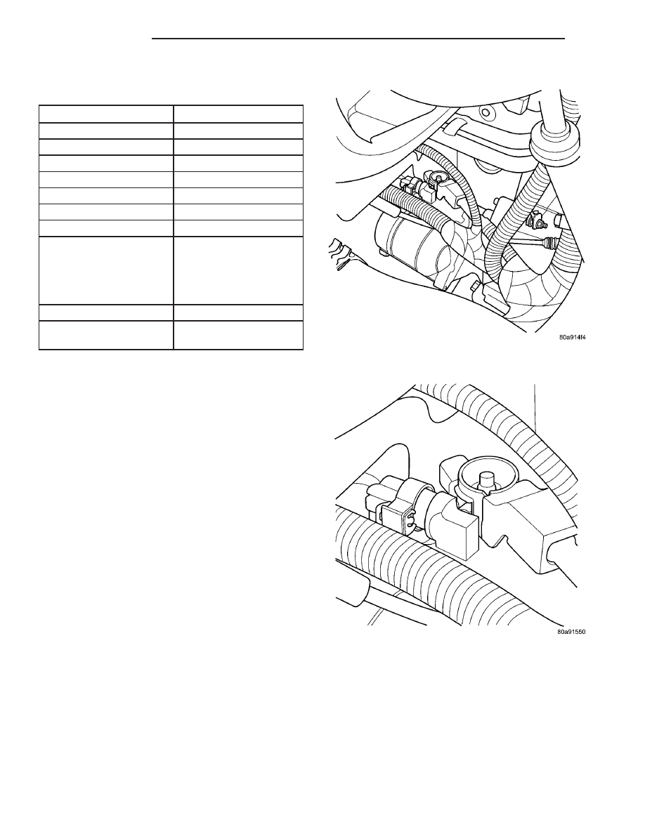
(1) Release hood latch and open hood (Fig. 2).
(2) Disconnect and isolate the battery negative

cable.

(3) Disconnect solenoid wire connector from termi-

nal (Fig. 3).

(4) Remove nut holding B+ wire to terminal.
(5) Disconnect solenoid and B+ wires from starter

terminals.

(6) Remove the lower bolt.
(7) Remove the upper bolt and ground wire (Fig.

4).

(8) Remove starter.

Fig. 2 STARTER 2.4L

Fig. 3 BATTERY CABLE AND FIELD WIRE 2.4L

8F - 34

STARTING

RS

STARTING (Continued)

REMOVAL - 3.3/3.8L

(1) Release hood latch and open hood.
(2) Disconnect and isolate the battery negative

cable.

(3) Hoist and support vehicle on safety stands.
(4) Remove nut holding B+ terminal to starter

solenoid (Fig. 5).

(5) Disconnect solenoid connector from starter.
(6) Remove bolts holding starter to transaxle bell-

housing (Fig. 6).

(7) Remove starter from bellhousing (Fig. 7).

(8) Separate starter spacer from transaxle bell-

housing.

INSTALLATION

INSTALLATION - 2.4L

(1) Place starter in position on vehicle.
(2) Install the lower bolts to hold starter to trans-

axle bellhousing.

(3) Install the upper bolt and ground wire (Fig. 4).
(4) Place solenoid and B+ wires in position on

starter terminals (Fig. 3).

(5) Install nut to hold B+ wire to terminal.
(6) Connect solenoid wire connector onto terminal.

Fig. 4 Upper Bolt and Ground Wire

Fig. 5 Starter

1 - SOLENOID CONNECTOR
2 - B+ CONNECTOR

Fig. 6 Starter Bolts

1 - STARTER
2 - STARTER BOLTS
3 - TRANSAXLE
4 - ENGINE MOUNT

Fig. 7 STARTER 3.3/3.8L

1 - BELL HOUSING PLATE
2 - FLYWHEEL
3 - ENGINE MOUNT
4 - STARTER
5 - SPACER

RS

STARTING

8F - 35

STARTER MOTOR (Continued)

(7) Connect battery negative cable.
(8) Verify starter operation.

INSTALLATION - 3.3/3.8L

(1) Place starter spacer in position on transaxle

bellhousing, flange toward flywheel.

(2) Place starter in position on bellhousing.

(3) Install bolts and ground wire (Fig. 4) to hold

starter to transaxle bellhousing.

(4) Connect solenoid connector into starter.
(5) Install nut to hold B+ terminal to starter sole-

noid.

(6) Lower vehicle.
(7) Connect battery negative cable.
(8) Verify starter operation.

8F - 36

STARTING

RS

STARTER MOTOR (Continued)

HEATED SYSTEMS

TABLE OF CONTENTS

page

page

HEATED GLASS . . . . . . . . . . . . . . . . . . . . . . . . . . . 1
HEATED MIRRORS . . . . . . . . . . . . . . . . . . . . . . . . . 5

HEATED SEAT SYSTEM . . . . . . . . . . . . . . . . . . . . . 7

HEATED GLASS

TABLE OF CONTENTS

page

page

HEATED GLASS

DESCRIPTION

. . . . . . . . . . . . . . . . . . . . . . . . . . 1

OPERATION

. . . . . . . . . . . . . . . . . . . . . . . . . . . . 1

DEFOGGER RELAY

DESCRIPTION

. . . . . . . . . . . . . . . . . . . . . . . . . . 2

REAR WINDOW DEFOGGER GRID

STANDARD PROCEDURE - GRID LINE

REPAIR REAR

. . . . . . . . . . . . . . . . . . . . . . . . . 2

REAR WINDOW DEFOGGER SWITCH

DESCRIPTION

. . . . . . . . . . . . . . . . . . . . . . . . . . 2

OPERATION

. . . . . . . . . . . . . . . . . . . . . . . . . . . . 2

WINDSHIELD GRID

DIAGNOSIS AND TESTING - SYSTEM TEST

. . . 3

STANDARD PROCEDURE - GRID LINE AND

TERMINAL REPAIR

. . . . . . . . . . . . . . . . . . . . . 3

HEATED GLASS

DESCRIPTION

The electrically heated Rear Window Defogger (Fig.

1), Heated Power Side View Mirrors, and Heated
Windshield Wiper De-icer (Fig. 2)is available on
select models.

OPERATION

The Rear Window Defogger(Refer to 8 - ELECTRI-

CAL/HEATED GLASS - DESCRIPTION) system con-
sists of two vertical bus bars linked by a series of
grid lines on the inside surface of the rear window.
The electrical circuit consists of the rear defogger

Fig. 1 REAR WINDOW DEFOGGER (TYPICAL)

1 - REAR DEFOGGER GRID
2 - REAR WINDOW

Fig. 2 (TYPICAL) Heated Windshield Wiper De-icer

1 - DEFROSTER OUTLET
2 - VIN #
3 - HEATED WINDSHIELD GRID

RS

HEATED SYSTEMS

8G - 1


Content   ..  92  93  94  95   ..