Chrysler Town, Dodge Caravan. Manual - part 76


  Index      Chrysler     Chrysler TOWN & COUNTRY, VOYAGER, Dodge Caravan - service repair manual 2001-2007 year


Search            


Content   ..  74  75  76  77   ..


Chrysler Town, Dodge Caravan. Manual - part 76


CONDITION

POSSIBLE CAUSE

CORRECTION

HEADPHONES
WILL NOT HOLD
A CHANNEL OR
HAVE STATIC

1. WEAK BATTERIES IN
THE HEADPHONES.

1. REPLACE BATTERIES.

2. CLOSENESS TO
RADIO TRANSMITTER
SUCH AS A RADIO
TOWER, AIRPORT
TRANSMITTER OR
SOME MOBILE
RADIOS.

2. MOVE TO AN AREA AWAY FREE FROM THESE
CONDITIONS.

REMOTE
CONTROL
INOPERATIVE

1. WEAK BATTERIES IN
THE REMOTE
CONTROL.

1. REPLACE BATTERIES.

2. OPERATION
CONSTRAINT OF
SYSTEM

2. MAKE SURE THAT REAR AUDIO IS IN A DIFFERENT MODE
THAN FRONT SPEAKERS. REMOTE CONTROL WILL NOT
WORK WHEN BOTH ARE IN THE SAME MODE.

ANTENNA BODY AND CABLE

DESCRIPTION

All models use a fixed-length stainless steel rod-

type antenna mast, installed at the right front fender
of the vehicle. The antenna mast is connected to the
center wire of the coaxial antenna cable, and is not
grounded to any part of the vehicle.

OPERATION

To minimize static, the antenna base must have a

good ground. The coaxial antenna cable shield (the
outer wire mesh of the cable) is grounded to the
antenna base and the radio chassis.

The antenna coaxial cable has an additional dis-

connect, located near the right end of the instrument
panel. This additional disconnect allows the instru-
ment panel assembly to be removed and installed
without removing the radio.

DIAGNOSIS AND TESTING - ANTENNA BODY
AND CABLE

WARNING: ON VEHICLES EQUIPPED WITH AIR-
BAGS,

REFER

TO

ELECTRICAL,

RESTRAINTS

BEFORE ATTEMPTING ANY STEERING WHEEL,
STEERING

COLUMN,

OR

INSTRUMENT

PANEL

COMPONENT DIAGNOSIS OR SERVICE. FAILURE
TO TAKE THE PROPER PRECAUTIONS COULD
RESULT IN ACCIDENTAL AIRBAG DEPLOYMENT
AND POSSIBLE PERSONAL INJURY.

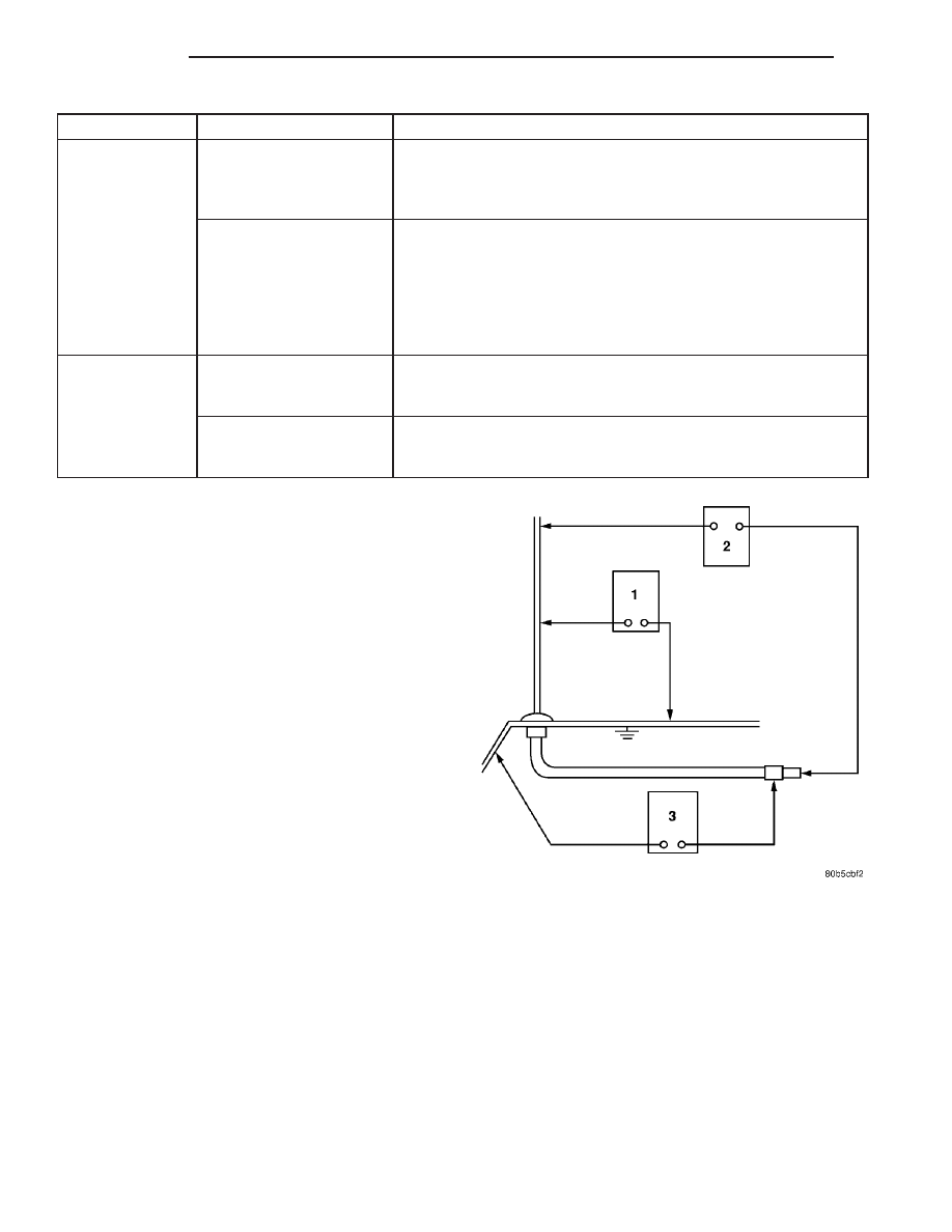
The ohmmeter test lead connections for each test

are shown in (Fig. 1).

TEST 1

Test 1 determines of the antenna mast is insulated

from the base. Proceed as follows:

(1) Unplug the antenna coaxial cable from the

radio chassis and isolate. Remove the antenna mast.

(2) Connect an ohmmeter test lead to the inside

center of the antenna base. Connect the other test
lead to a metallic portion on the outside of the
antenna base. Check for continuity.

(3) There should be no continuity. If continuity is

found, replace the faulty or damaged antenna base
and cable assembly.

Fig. 1 Antenna Test Points

8A - 4

AUDIO

RS

AUDIO/VIDEO (Continued)

TEST 2

Test 2 checks the antenna for an open circuit as

follows:

(1) Unplug the antenna coaxial cable connector

from the radio chassis. Remove the antenna mast.

(2) Connect an ohmmeter test lead to the inside

center of the antenna base. Connect the other test
lead to the center pin of the antenna coaxial cable
connector.

(3) Continuity should exist (the ohmmeter should

only register a fraction of an ohm). High or infinite
resistance indicates damage to the base and cable
assembly. Replace the faulty base and cable if
required.

TEST 3

Test 3 checks the condition of the ground between

the antenna base and the vehicle body as follows:

(1) Connect one ohmmeter test lead to the fender

on an exposed metal area. Connect the other test
lead to the outer crimp on the antenna coaxial cable
connector.

(2) The resistance should be less than (1) ohm.
(3) If the resistance is more than (1) ohm, clean

and/or tighten the antenna base to the fender mount-
ing hardware.

REMOVAL

(1) Disconnect and isolate the battery negative

cable.

(2) Remove glove box from instrument panel,

(Refer to 23 - BODY/INSTRUMENT PANEL/GLOVE
BOX - REMOVAL).

(3) Disconnect antenna cable connector from exten-

sion cable (Fig. 2).

(4) Remove right kick trim panel.
(5) Disengage rubber grommet insulator from door

hinge pillar.

(6) Pull antenna cable through hinge pillar into

opening between door hinges.

(7) Hoist and support vehicle on safety stands.
(8) Remove front wheel.
(9) Remove front wheelhouse splash shield. (Refer

to

23

-

BODY/EXTERIOR/LF

WHEELHOUSE

SPLASH SHIELD - REMOVAL).

Fig. 2 Antenna Cable

1 - CAP NUT
2 - ADAPTER
3 - FENDER
4 - CABLE TO RADIO (EXTENSION CABLE)

5 - A-PILLAR
6 - RUBBER GROMMET
7 - ANTENNA CABLE AND BODY ASSEMBLY
8 - RUBBER GROMMET

RS

AUDIO

8A - 5

ANTENNA BODY AND CABLE (Continued)

(10) Remove antenna mast from antenna base

(Fig. 3).

(11) Using cap nut tool, remove cap nut holding

antenna base to front fender (Fig. 4).

(12) Remove

antenna

base

from

under

front

fender.

INSTALLATION

(1) Install antenna base to underside of front

fender.

(2) Install cap nut holding antenna base to front

fender.

(3) Install antenna mast to antenna base.
(4) Install front wheelhouse splash shield.
(5) Install front wheel.
(6) Lower vehicle.
(7) Push antenna cable through opening in hinge

pillar.

(8) Insert rubber grommet into door hinge pillar.
(9) Install kick panel.
(10) Connect antenna cable connector to extension

cable.

(11) Install glove box to instrument panel.
(12) Connect the battery negative cable.

ANTENNA MODULE - EXPORT

DESCRIPTION

The antenna module is an electromagnetic circuit

component designed to capture and enhance RF
(Radio Frequency) signals in both the AM and FM
broadcast bands. The antenna module is mounted to
the right rear roof rail under the headliner. The mod-
ule is grounded through the mounting bracket and
fastener. The module has a two wire electrical con-
nector that connects to the integral radio antenna,
located on the right rear quarter glass. There is also
an electrical connector for battery voltage and a coax
cable connector.

OPERATION

The antenna module receives both AM and FM

radio signals supplied by the side window integral
radio antenna system and selectively amplifies them.
The amplified signal is then sent through the body
length coax cable to the radio input.

Fig. 3 Antenna Mast

1 - ANTENNA MAST
2 - ADAPTER
3 - CAP NUT

Fig. 4 Antenna Cap Nut

1 - CAP NUT
2 - ANTENNA ADAPTER
3 - TOOL

8A - 6

AUDIO

RS

ANTENNA BODY AND CABLE (Continued)

DIAGNOSIS AND TESTING - ANTENNA MODULE - EXPORT

CONDITION

POSSIBLE CAUSES

CORRECTION

NO AM RECEPTION,

WEAK FM RECEPTION

1. Antenna module to antenna
connector open or disconnected.

1. Repair open, reconnect
antenna module connector to
glass mounted antenna.

2. Coax open or disconnected.

2. Repair open, reconnect coax.

3. No battery power at antenna
module.

3. Check fuse. if okay, repair
open in battery voltage circuit.

NO AM OR FM

RECEPTION

1. Coax disconnected at radio.

1. Reconnect coax.

2. Coax shorted to ground.

2. Repair or Replace coax

WEAK OR NO AM/FM

RECEPTION

1. Antenna Module faulty.

1. Substitute known good
module. If reception improves,
Antenna Module was faulty.

REMOVAL

(1) Disconnect and isolate the battery negative

cable.

(2) Lower

headliner

as

necessary

to

access

antenna module (Fig. 5).

(3) Disconnect antenna coax cable lead and electri-

cal harness connector from antenna module.

(4) Disconnect the antenna module connector from

the quarter glass.

(5) Remove the mounting screw and the antenna

module.

INSTALLATION

(1) Install the antenna module and the mounting

fastener.

(2) Connect the antenna connector to the quarter

glass.

(3) Connect the antenna lead and electrical con-

nector to the antenna module.

(4) Raise and install headliner.
(5) Connect the battery negative cable.

CD CHANGER

DESCRIPTION

The 6 Disc In-Dash CD Changer (if equipped) is

located in the instrument panel below the radio. The
remote changer does not use a cartridge or magazine
for the CD’s. Up to 6 CD’s can be directly loaded into
this unit.

OPERATION

Due to its compact design, the CD changer can

carry out only one operation at a time. For example,
you can not load a new disc while playing another at
the same time. Each operation happens sequentially.

The radio unit provides control over all features of

the CD changer with the exception of the CD load
and eject functions, which are controlled by buttons
located on the front of the CD changer. All features
you would expect, such as Disc Up/Down, Track
Up/Down, Random and Scan are controlled by the
radio, which also displays all relevant CD changer
information on the radio display.

The CD changer contains a Eject button, six disc

buttons, an indicator LED for each of the six disc
positions as well as an illuminated disc opening. The
individual LED indicates whether a CD is currently
loaded in that particular chamber of the CD changer.
Pressing the individual button for a particular cham-
ber, then the Eject button will eject a disc currently
present in that chamber. If the chamber is currently
empty, actuating the individual button will position

Fig. 5 ANTENNA MODULE

1 - ANTENNA MODULE
2 - ANTENNA MODULE CONNECTOR

RS

AUDIO

8A - 7

ANTENNA MODULE - EXPORT (Continued)


Content   ..  74  75  76  77   ..