Chrysler Town, Dodge Caravan. Manual - part 46


  Index      Chrysler     Chrysler TOWN & COUNTRY, VOYAGER, Dodge Caravan - service repair manual 2001-2007 year


Search            


Content   ..  44  45  46  47   ..


Chrysler Town, Dodge Caravan. Manual - part 46


movement

with

rubber

isolated

suspension

crossmember.

(3) Install the four chassis brake tubes into the

outlet ports of the junction block. Tighten all 6 tube
nuts to a torque of 17 N·m (145 in. lbs.).

(4) If the vehicle is equipped with speed control,

perform the following:

(a) Install the speed control servo with its

mounting nuts.

(b) Connect the wiring harness to the speed con-

trol servo.

(c) Install the battery tray (Refer to 8 - ELEC-

TRICAL/BATTERY SYSTEM/TRAY - INSTALLA-
TION).

(d) Install the screw securing the coolant filler

neck to the battery tray.

(e) Reconnect the vacuum hose connector at the

tank built into the battery tray.

(f) Install the battery (Refer to 8 - ELECTRI-

CAL/BATTERY SYSTEM/BATTERY - INSTALLA-
TION).

(g) Install the battery shield.

(5) Remove the brake pedal holder.
(6) Connect negative cable back on negative post of

the battery.

(7) Bleed the brake system thoroughly to ensure

that all air has been expelled from the hydraulic sys-
tem. (Refer to 5 - BRAKES - STANDARD PROCE-
DURE).

(8) Road test the vehicle to verify proper operation

of the brake system.
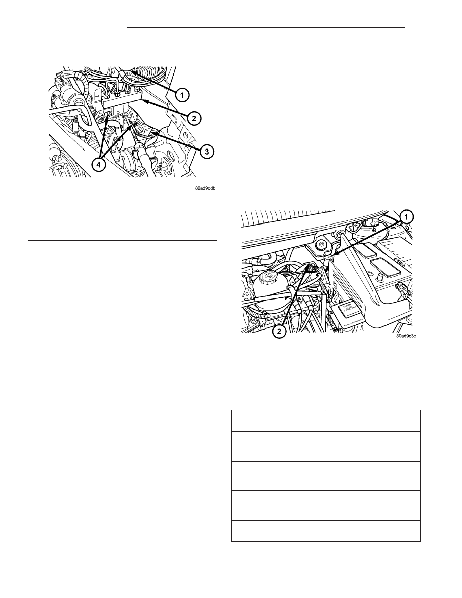
MASTER CYLINDER

DESCRIPTION

DESCRIPTION

The master cylinder is located on the power brake

booster in the engine compartment on the driver’s
side (Fig. 46). This vehicle uses 3 different master
cylinders. Master cylinder usage depends on what
type of brake system the vehicle is equipped with.

CAUTION: Master cylinders are not interchangeable
between systems. Performance and stopping dis-
tance issues will result if the incorrect master cyl-
inder is installed on the vehicle.

For information on master cylinder application,

bore and type, view the following table:

BRAKE SYSTEM

MASTER CYLINDER

BORE/TYPE

Disc/Drum - ABS

23.8 mm (15/16 in.)

Conventional

Compensating Port

Disc/Drum - Non-ABS

23.8 mm (15/16 in.)

Conventional

Compensating Port

Disc/Disc - ABS

25.4 mm (1.0 in.)

Conventional

Compensating Port

Disc/Disc ABS With
Traction Control

25.4 mm (1.0 in.) Dual

Center Port

Fig. 45 NON-ABS JUNCTION BLOCK

1 - MASTER CYLINDER
2 - JUNCTION BLOCK
3 - SUSPENSION CROSSMEMBER
4 - MOUNTING BOLTS

Fig. 46 Master Cylinder And Booster Location

1 - MASTER CYLINDER
2 - POWER BRAKE BOOSTER

5 - 34

BRAKES - BASE

RS

JUNCTION BLOCK (Continued)

CAUTION: When replacing a master cylinder, be
sure to use the correct master cylinder for the type
of brake system the vehicle is equipped with.

The body of the master cylinder is an anodized alu-

minum casting. It has a machined bore to accept the
master cylinder pistons and threaded ports with
seats for the hydraulic brake line connections.

The brake fluid reservoir is mounted on the top of

the master cylinder. It is made of a see-through
polypropylene type plastic for easy fluid level view-
ing. A brake fluid level switch is attached to the
brake fluid reservoir.

The master cylinder is not a repairable component

and must be replaced if diagnosed to be functioning
improperly. The brake fluid reservoir and brake fluid
level switch can be replaced separately.

CAUTION: Do not hone the bore of the cylinder as
this will remove the anodized surface from the bore.

DESCRIPTION - RHD

The master cylinder used on right hand drive

(RHD) vehicles functions similarly to that used on
left hand drive (LHD) vehicles. The RHD master cyl-
inder, as well as the RHD power brake booster, is
located in the same area, but lower in the engine
compartment than LHD models (Fig. 47). For that
reason an extension manifold is placed between the
fluid reservoir and master cylinder housing allowing
the fluid reservoir to be positioned in the same loca-
tion as on LHD models.

OPERATION

When the brake pedal is depressed, the master cyl-

inder primary and secondary pistons apply brake
pressure through the chassis tubes to the brakes at
each tire and wheel assembly.

The master cylinder primary outlet port supplies

hydraulic pressure to the right front and left rear
brakes. The secondary outlet port supplies hydraulic
pressure to the left front and right rear brakes.

STANDARD PROCEDURE - MASTER CYLINDER
BLEEDING

CAUTION: When clamping master cylinder in vise,
only clamp master cylinder by its mounting flange.
Do not clamp master cylinder piston rod, reservoir,
seal or body.

(1) Clamp master cylinder in a vise.

NOTE: Use correct bleeder tubes when bleeding
master cylinder. Master cylinder outlet ports vary in
size and type depending on whether master cylin-
der is for a vehicle equipped with traction control or
not. Traction control equipped master cylinders
require the additional use of ISO style flare adapt-
ers supplied in Special Tool Package 8822 to be
used in conjunction with Bleeder Tubes, Special
Tool Package 8358.

(2) Attach special tools for bleeding master cylin-

der in the following fashion:

(a) For non-traction control equipped mas-

ter cylinders, thread a Bleeder Tube, Special Tool
8358–1, into each outlet port. Tighten each tube to
17 N·m (145 in. lbs.) torque. Flex bleeder tubes and
place open ends into mouth of fluid reservoir as far
down as possible (Fig. 48).

(b) For traction control equipped master

cylinders,

thread

one

Adapter,

Special

Tool

8822–2, in each outlet port. Tighten Adapters to 17
N·m (145 in. lbs.) torque. Next, thread a Bleeder
Tube, Special Tool 8358–1, into each Adapter.
Tighten each tube to 17 N·m (145 in. lbs.) torque.
Flex bleeder tubes and place open ends into mouth
of fluid reservoir as far down as possible (Fig. 48).

NOTE: Make sure open ends of bleeder tubes stay
below surface of brake fluid once reservoir is filled
to proper level.

(3) Fill brake fluid reservoir with Mopar

t brake

fluid or equivalent conforming to DOT 3 (DOT 4 and
DOT 4+ are acceptable) specifications. Make sure
fluid level is above tips of bleeder tubes in reservoir
to ensure no air is ingested during bleeding.

Fig. 47 RHD MASTER CYLINDER AND POWER

BRAKE BOOSTER

1 - POWER BRAKE BOOSTER
2 - BRAKE FLUID LEVEL SWITCH
3 - FLUID RESERVOIR
4 - MASTER CYLINDER

RS

BRAKES - BASE

5 - 35

MASTER CYLINDER (Continued)

(4) Using a wooden dowel as a pushrod (Fig. 48),

slowly depress master cylinder pistons, then release
pressure, allowing pistons to return to released posi-
tion. Repeat several times until all air bubbles are
expelled. Make sure fluid level stays above tips of
bleeder tubes in reservoir while bleeding.

(5) Remove bleeder tubes from master cylinder

outlet ports, then plug outlet ports and install fill cap
on reservoir.

(6) Remove master cylinder from vise.
(7) Install master cylinder on vehicle. (Refer to 5 -

BRAKES - BASE/HYDRAULIC/MECHANICAL/MAS-
TER CYLINDER - INSTALLATION)

REMOVAL

REMOVAL - LHD

CAUTION: Vacuum in the power brake booster must
be pumped down (removed) before removing mas-
ter cylinder from power brake booster. This is nec-
essary to prevent the power brake booster from
sucking in any contamination as the master cylin-
der is removed. This can be done simply by pump-
ing the brake pedal, with the vehicle’s engine not
running, until a firm feeling brake pedal is achieved.

(1) With engine not running, pump brake pedal

until a firm pedal is achieved (4-5 strokes).

(2) Disconnect negative battery terminal.

(3) Disconnect positive battery terminal.
(4) Remove battery shield.
(5) Remove nut and clamp securing battery to tray,

remove battery.

(6) Thoroughly clean all surfaces of the brake fluid

reservoir and master cylinder. Use only solvent such
as Mopar

t Brake Parts Cleaner or equivalent.

(7) Remove wiring harness connector from brake

fluid level switch in master cylinder brake fluid res-
ervoir (Fig. 49).

(8) Disconnect primary and secondary brake tubes

from master cylinder housing (Fig. 49). Install seal-
ing plugs in the now open brake tube outlet ports.

CAUTION: Before removing the master cylinder
from the power brake vacuum booster, the master
cylinder and vacuum booster must be thoroughly
cleaned. This must be done to prevent dirt particles
from falling into the power brake vacuum booster.

(9) Clean area where master cylinder assembly

attaches to power brake booster. Use only a solvent
such as Mopar

t Brake Parts Cleaner or equivalent.

(10) Remove two nuts attaching master cylinder to

power brake booster (Fig. 50).

(11) Slide master cylinder straight out of power

brake booster.

CAUTION: A seal on the rear of the master cylinder
is used to create the seal for holding vacuum in the
power brake vacuum booster. The vacuum seal on
the master cylinder MUST be replaced whenever the
master cylinder is removed from the power brake
vacuum booster.

Fig. 48 Master Cylinder Set Up For Bleeding

1 - BLEEDER TUBES 8358
2 - WOODEN DOWEL
3 - ADAPTER 8822-2 (USE ONLY ON TRACTION CONTROL
EQUIPPED MASTER CYLINDERS)
4 - ADAPTER 8822-2 (USE ONLY ON TRACTION CONTROL
EQUIPPED MASTER CYLINDERS)

Fig. 49 MASTER CYLINDER AND BOOSTER

1 - POWER BRAKE BOOSTER
2 - BOOSTER IDENTIFICATION LABEL
3 - FLUID LEVEL SWITCH CONNECTOR
4 - PRIMARY BRAKE TUBE NUT
5 - SECONDARY BRAKE TUBE NUT
6 - MASTER CYLINDER

5 - 36

BRAKES - BASE

RS

MASTER CYLINDER (Continued)

(12) Remove vacuum seal located on the mounting

flange of the master cylinder. The vacuum seal is
removed from master cylinder by carefully pulling it
off the rear of master cylinder. Do not attempt to
pry the seal off the master cylinder by inserting
a sharp tool between seal and master cylinder
casting.

REMOVAL - RHD

CAUTION: Vacuum in the power brake booster must
be pumped down (removed) before removing mas-
ter cylinder from power brake booster. This is nec-
essary to prevent the power brake booster from
sucking in any contamination as the master cylin-
der is removed. This can be done simply by pump-
ing the brake pedal, with the vehicle’s engine not
running, until a firm feeling brake pedal is achieved.

(1) With engine not running, pump brake pedal

until a firm pedal is achieved (4 or 5 strokes).

(2) Disconnect negative battery terminal.
(3) Disconnect positive battery terminal.
(4) Remove battery shield.
(5) Remove nut and clamp securing battery to tray,

remove battery.

(6) Thoroughly clean all surfaces of the brake fluid

reservoir and master cylinder. Use only solvent such
as Mopar

t Brake Parts Cleaner or equivalent.

(7) Remove wiring harness connector from brake

fluid level switch in master cylinder brake fluid res-
ervoir (Fig. 47).

(8) Disconnect primary and secondary brake tubes

from master cylinder housing (Fig. 51). Install seal-
ing plugs in the now open brake tube outlet ports.

CAUTION: Before removing the master cylinder
from the power brake vacuum booster, the master
cylinder and vacuum booster must be thoroughly
cleaned. This must be done to prevent dirt particles
from falling into the power brake vacuum booster.

(9) Clean area where master cylinder assembly

attaches to power brake booster. Use only a solvent
such as Mopar

t Brake Parts Cleaner or equivalent.

(10) Remove two nuts attaching master cylinder to

power brake booster (Fig. 51).

(11) Slide master cylinder straight out of power

brake booster.

CAUTION: A seal on the rear of the master cylinder
is used to create the seal for holding vacuum in the
power brake vacuum booster. The vacuum seal on
the master cylinder MUST be replaced whenever the
master cylinder is removed from the power brake
vacuum booster.

(12) Remove vacuum seal located on the mounting

flange of the master cylinder. The vacuum seal is
removed from master cylinder by carefully pulling it
off the rear of master cylinder. Do not attempt to
pry the seal off the master cylinder by inserting
a sharp tool between seal and master cylinder
casting.

DISASSEMBLY - MASTER CYLINDER (FLUID
RESERVOIR)

(1) Clean master cylinder housing and brake fluid

reservoir. Use only a solvent such as Mopar Brake
Parts Cleaner or an equivalent.

Fig. 50 MASTER CYLINDER MOUNTING

1 - MASTER CYLINDER MOUNTING NUTS
2 - MASTER CYLINDER
3 - SECONDARY TUBE NUT AT ICU
4 - PRIMARY TUBE NUT AT ICU

Fig. 51 RHD MASTER CYLINDER MOUNTING

1 - PRIMARY BRAKE TUBE NUT
2 - SECONDARY BRAKE TUBE NUT
3 - MASTER CYLINDER MOUNTING NUTS

RS

BRAKES - BASE

5 - 37

MASTER CYLINDER (Continued)


Content   ..  44  45  46  47   ..