Chrysler Town, Dodge Caravan. Manual - part 43


  Index      Chrysler     Chrysler TOWN & COUNTRY, VOYAGER, Dodge Caravan - service repair manual 2001-2007 year


Search            


Content   ..  41  42  43  44   ..


Chrysler Town, Dodge Caravan. Manual - part 43


(12) Remove the leading brake shoe assembly to

brake support plate hold down spring and pin (Fig.
28) from the brake shoe. Remove the leading brake
shoe from the brake support plate.

(13) Remove the park brake actuator (Fig. 29)

from the leading brake shoe and transfer to the
replacement brake shoe.

INSPECTION - REAR DRUM BRAKE SHOE
LINING

(1) Remove the tire and wheel assembly from the

vehicle

(2) Remove the rear brake adjusting hole plug

found in the brake support.

(3) Insert a thin screwdriver into brake adjusting

hole to hold the adjusting lever away from the
notches on the adjusting screw star wheel.

(4) Insert Tool C-3784 into brake adjusting hole

and engage notches of brake adjusting screw star
wheel. Release brake by prying down with adjusting
tool.

(5) Remove the rear brake drum from the rear hub

and bearing assembly. (Refer to 5 - BRAKES/HY-
DRAULIC/MECHANICAL/DRUM - REMOVAL)

(6) Inspect brake lining for wear, shoe alignment,

and or contamination from grease or brake fluid.

INSTALLATION - REAR DRUM BRAKE SHOES

(1) Lubricate the eight shoe contact areas on the

support plate and

anchor, (Fig. 30) using

the

required special Mopar

t Brake Lubricant or equiva-

lent.

(2) Install leading brake shoe on brake support

plate. Install the leading brake shoe hold down
spring and pin (Fig. 28) on the brake shoe.

(3) Install the park brake actuator strut (Fig. 31)

on the leading brake shoe. Then install the park
brake actuator lever on the strut (Fig. 31).

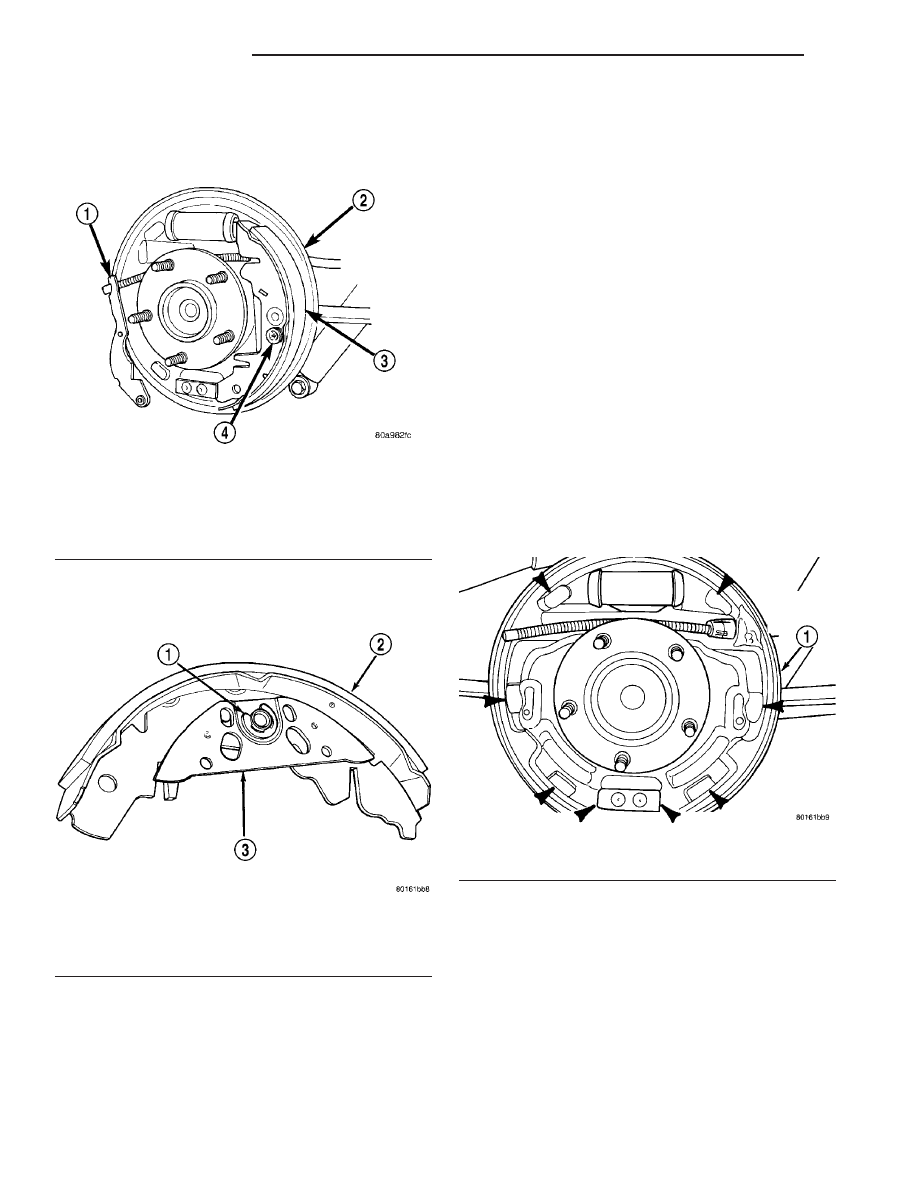
Fig. 28 Leading Brake Shoe Hold Down Spring And

Pin

1 - PARK BRAKE ACTUATING LEVER
2 - BRAKE SUPPORT PLATE
3 - LEADING BRAKE SHOE
4 - HOLD DOWN SPRING AND PIN

Fig. 29 Park Brake Actuator Plate

1 - RETAINING CLIP
2 - BRAKE SHOE ASSEMBLY
3 - ACTUATOR PLATE

Fig. 30 Brake Support Plate Contact Areas

1 - REAR BRAKE SUPPORT PLATE

5 - 22

BRAKES - BASE

RS

BRAKE PADS/SHOES - REAR DRUM (Continued)

(4) Install the automatic adjuster screw on the

leading brake shoe. Then install the trailing brake
shoe on the park brake actuating lever and park
brake actuating strut (Fig. 27). Position trailing
brake shoe on brake support plate.

(5) Install the brake shoe hold down pin and

spring on the trailing brake shoe (Fig. 26).

(6) Install the brake shoe to brake shoe upper

return spring (Fig. 25).

CAUTION: When installing the tension clip on the
automatic adjuster, it must be located on only the
threaded area of the adjuster assembly (Fig. 24). If
it is located on a non-threaded area of the adjuster,
the function of the automatic adjuster will be
affected.

(7) Install the tension clip (Fig. 24) attaching the

upper return spring to the automatic adjuster assem-
bly.

(8) Install the brake shoe to brake shoe lower

return springs on the brake shoes (Fig. 22) and (Fig.
23).

(9) Install automatic adjustment lever on the lead-

ing brake shoe of the rear brake assembly (Fig. 21).

(10) Install the actuating spring on the automatic

adjustment lever and leading brake shoe assembly
(Fig. 20).

(11) Verify that the automatic adjuster lever has

positive contact with the star wheel on the automatic
adjuster assembly.

(12) When all components of both rear brake

assemblies are correctly and fully installed, remove
the locking pliers from the front park brake cable.

(13) Adjust brake shoes assemblies so as not to

interfere with brake drum installation.

(14) Install the rear brake drums on the hubs.
(15) Adjust rear brake shoes.
(16) Install the wheel and tire assembly.
(17) Tighten the wheel mounting stud nuts in

proper sequence until all nuts are torqued to half
specification. Then repeat the tightening sequence to
the full specified torque of 135 N·m (100 ft. lbs.).

(18) Lower the vehicle.
(19) Push the parking brake lever (pedal) to the

floor once and release pedal. This will automatically
remove the slack from and correctly adjust the park-
ing brake cables.

(20) Road test vehicle. The automatic adjuster will

continue the brake adjustment during the road test
of the vehicle.

ADJUSTMENTS

ADJUSTMENT - REAR DRUM BRAKE SHOES

NOTE: Normally, self-adjusting drum brakes do not
require manual brake shoe adjustment. Although, in
the event of a brake shoe replacement, it is advis-
able to make the initial adjustment manually to
speed up the adjusting time.

NOTE: Before raising the vehicle, verify the parking
brake lever is fully released.

(1) Raise the vehicle. (Refer to LUBRICATION &

MAINTENANCE/HOISTING - STANDARD PROCE-
DURE).

(2) Remove rubber plug from rear brake adjusting

hole in the rear brake support plate.

(3) Insert a thin screwdriver through the adjusting

hole in the support plate and against the star wheel
of the adjusting screw. Move handle of the tool
upward rotating the star wheel until a slight drag is
felt when tire and wheel assembly is rotated.

(4) Insert a second thin screwdriver or piece of

welding rod into brake adjusting hole and push the
adjusting lever out of engagement with the star
wheel. Care should be taken so as not to bend
adjusting lever or distort lever spring.

(5) While

holding

the

adjusting

lever

out

of

engagement, back off the star wheel just enough to
ensure a free wheel with no brake shoe drag.

(6) Repeat the above adjustment at the other rear

wheel.

(7) Install the adjusting hole rubber plugs back in

the rear brake support plates.

(8) Lower the vehicle.

Fig. 31 Park Brake Components Assembled On

Leading Brake Shoe

1 - PARK BRAKE CABLE
2 - LEADING BRAKE SHOE
3 - PARK BRAKE ACTUATING STRUT
4 - PARK BRAKE ACTUATING LEVER
5 - BRAKE SUPPORT PLATE

RS

BRAKES - BASE

5 - 23

BRAKE PADS/SHOES - REAR DRUM (Continued)

DISC BRAKE CALIPER -
FRONT

REMOVAL

REMOVAL - FRONT DISC BRAKE CALIPER
(DISC/DISC BRAKES)

(1) Depress the brake pedal past its first inch of

travel and hold it in this position using a brake pedal
depressor (holding) tool. This is done to isolate the
master cylinder from the brake hydraulic system dis-
allowing the brake fluid to completely drain out of
the brake fluid reservoir.

(2) Raise the vehicle. (Refer to LUBRICATION &

MAINTENANCE/HOISTING - STANDARD PROCE-
DURE).

(3) Remove front wheel and tire assembly.
(4) Remove the banjo bolt connecting the brake

hose to the brake caliper. There are two washers (one
on each side of the brake hose fitting) that will come
off with the banjo bolt. Discard these washers.

(5) Remove the 2 caliper guide pin bolts.
(6) Remove the brake caliper from the adapter.

REMOVAL - FRONT DISC BRAKE CALIPER
(DISC/DRUM BRAKES)

(1) Using a brake pedal holding tool, depress the

brake pedal past its first one inch of travel and hold
it in this position. This will isolate the master cylin-
der from the brake hydraulic system and will not
allow the brake fluid to drain out of the master cyl-
inder reservoir when the lines are opened.

(2) Raise the vehicle. Refer to HOISTING in

LUBRICATION AND MAINTENANCE.

(3) Remove the front tire and wheel assembly.
(4) Remove the banjo bolt connecting the brake

hose to the brake caliper (Fig. 32). There are two
washers (one on each side of the flex hose fitting)
that will come off with the banjo bolt. Discard the
washers.

(5) Remove the two brake caliper guide pin bolts

(Fig. 32).

(6) Remove the disc brake caliper from the disc

brake adapter.

DISASSEMBLY

DISASSEMBLY - CALIPER GUIDE PIN
BUSHINGS (DISC/DISC BRAKES)

Before disassembling the brake caliper, clean and

inspect it. Refer to CLEANING or INSPECTION in
this section.

(1) Using your fingers, collapse one side of the rub-

ber guide pin bushing. Pull the guide pin bushing out
the other side of the brake caliper mounting boss.

(2) Repeat this procedure on the remaining bush-

ing.

DISASSEMBLY - CALIPER PISTON AND SEAL

WARNING: UNDER NO CONDITION SHOULD HIGH
PRESSURE AIR EVER BE USED TO REMOVE A PIS-
TON FROM A CALIPER BORE. PERSONAL INJURY
COULD RESULT FROM SUCH A PRACTICE.

NOTE: Before disassembling the brake caliper,
clean and inspect it. Refer to CLEANING AND
INSPECTION in this section.

NOTE: The safest way to remove the piston from
the caliper bore is to use the hydraulic pressure of
the vehicle’s brake system.

(1) Following the removal procedure in DISC

BRAKE SHOES found in this section, remove the
caliper from the brake rotor and hang the assembly
on a wire hook away from rotor and body of the vehi-
cle so brake fluid cannot get on these components.
Remove the brake shoes, and place a small piece of
wood between the piston and caliper fingers.

(2) Carefully depress the brake pedal to hydrauli-

cally push piston out of its bore. Once completed,
apply and hold down the brake pedal to any position
beyond the first inch of pedal travel using a brake
pedal holding tool. This will prevent the fluid in the

Fig. 32 Brake Caliper Mounting (Typical)

1 - BRAKE HOSE
2 - ADAPTER MOUNTING BOLTS
3 - BANJO BOLT
4 - CALIPER GUIDE PIN BOLTS

5 - 24

BRAKES - BASE

RS

master cylinder reservoir from completely draining
out.

(3) Disconnect the brake fluid flex hose from the

caliper assembly and remove it from the vehicle.

CAUTION: Do not use excessive force when clamp-
ing caliper in vise. Excessive vise pressure will
cause bore distortion.

(4) Mount the caliper in a vise equipped with pro-

tective jaws.

(5) Remove the piston dust boot from the caliper

and discard.

NOTE: Do not use a screw driver or other metal tool
for seal removal. Using such tools can scratch the
bore or leave burrs on the seal groove edges.

(6) Using a soft tool such as a plastic trim stick,

work the piston seal out of its groove in caliper pis-
ton bore (Fig. 33). Discard the old seal.

(7) Clean the piston bore and drilled passage ways

using alcohol or a suitable solvent. Wipe it dry using
only a lint-free cloth.

(8) Inspect the piston bore for scoring or pitting.

Bores that show light scratches or corrosion can usu-
ally be cleared of the light scratches or corrosion
using crocus cloth.

CLEANING - CALIPER

WARNING: DUST AND DIRT ACCUMULATING ON
BRAKE PARTS DURING NORMAL USE MAY CON-
TAIN ASBESTOS FIBERS FROM PRODUCTION OR
AFTERMARKET

BRAKE

LININGS.

BREATHING

EXCESSIVE

CONCENTRATIONS

OF

ASBESTOS

FIBERS CAN CAUSE SERIOUS BODILY HARM.
EXERCISE

CARE

WHEN

SERVICING

BRAKE

PARTS. DO NOT SAND OR GRIND BRAKE LINING
UNLESS EQUIPMENT USED IS DESIGNED TO CON-
TAIN THE DUST RESIDUE. DO NOT CLEAN BRAKE
PARTS

WITH

COMPRESSED AIR

OR

BY DRY

BRUSHING. CLEANING SHOULD BE DONE BY
DAMPENING THE BRAKE COMPONENTS WITH A
FINE MIST OF WATER, THEN WIPING THE BRAKE
COMPONENTS CLEAN WITH A DAMPENED CLOTH.
DISPOSE OF CLOTH AND ALL RESIDUE CONTAIN-
ING ASBESTOS FIBERS IN AN IMPERMEABLE
CONTAINER WITH THE APPROPRIATE LABEL. FOL-
LOW PRACTICES PRESCRIBED BY THE OCCUPA-
TIONAL SAFETY AND HEALTH ADMINISTRATION
(OSHA) AND THE ENVIRONMENTAL PROTECTION
AGENCY (EPA) FOR THE HANDLING, PROCESSING,
AND DISPOSING OF DUST OR DEBRIS THAT MAY
CONTAIN ASBESTOS FIBERS.

To clean or flush the internal passages of the brake

caliper, use fresh brake fluid or Mopar

t Non-Chlori-

nated Brake Parts Cleaner. Never use gasoline, ker-
osene, alcohol, oil, transmission fluid or any fluid
containing mineral oil to clean the caliper. These flu-
ids will damage rubber cups and seals.

INSPECTION - CALIPER

Inspect the disc brake caliper for the following:
• Brake fluid leaks in and around boot area and

inboard lining

• Ruptures, brittleness or damage to the piston

dust boot

• Damaged, dry or brittle guide pin dust boots
If caliper fails inspection, disassemble and recondi-

tion caliper, replacing the seals and dust boots.

ASSEMBLY

ASSEMBLY - CALIPER GUIDE PIN BUSHINGS
(DISC/DISC BRAKES)

(1) Fold the guide pin bushing in half lengthwise.

NOTE: To avoid damage to the bushing, do not use
a sharp object to install the guide pin bushing.

(2) Insert the folded bushing into the caliper

mounting boss using your fingers from the rear of
the caliper.

Fig. 33 Removing Piston Seal

1 - PLASTIC TRIM STICK
2 - CALIPER
3 - PISTON SEAL GROOVE
4 - PISTON SEAL

RS

BRAKES - BASE

5 - 25

DISC BRAKE CALIPER - FRONT (Continued)


Content   ..  41  42  43  44   ..