Chrysler Town, Dodge Caravan. Manual - part 16


  Index      Chrysler     Chrysler TOWN & COUNTRY, VOYAGER, Dodge Caravan - service repair manual 2001-2007 year


Search            


Content   ..  14  15  16  17   ..


Chrysler Town, Dodge Caravan. Manual - part 16


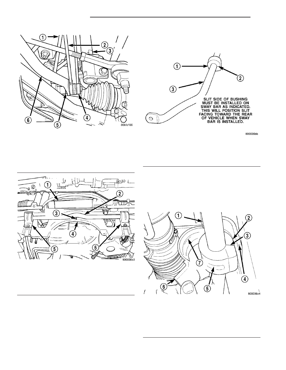
(1) If the stabilizer bar to front suspension cradle

bushings require replacement at time of inspection,
install new bushings before installing stabilizer bar.
Bushings are replaced by opening slit on bushings
and peeling them off stabilizer bar. Install new bush-
ings on stabilizer bar by spreading bushing at slit
and forcing them on the stabilizer bar. Bushings
must be installed on stabilizer bar so slit in
bushing will be facing toward the rear of vehi-

cle with the square corner toward the ground,
when the stabilizer bar is installed on the vehi-
cle (Fig. 35).

(2) Position stabilizer bar into front suspension

cradle so stabilizer bar bushings are aligned with
depressions in cradle. Install stabilizer bar bushing
retainers onto crossmember aligning raised bead on
retainer with cutouts in bushings (Fig. 36). Do not
tighten Stabilizer bar bushing retainers bolts at
this time.

Fig. 33 Stabilizer Bar Link To Stabilizer Bar

Attachment

1 - RATCHET
2 - WRENCH
3 - STRUT
4 - STABILIZER BAR LINK
5 - NUT
6 - STABILIZER BAR

Fig. 34 Front Stabilizer Bar Retainers

1 - STEERING GEAR
2 - STABILIZER BAR
3 - RAISED BEAD
4 - FRONT CRADLE CROSSMEMBER
5 - RETAINERS

Fig. 35 Correctly Installed Stabilizer Bar To Cradle

Bushing

1 - SWAY BAR ISOLATOR BUSHING
2 - SLIT IN SWAY BAR BUSHING
3 - SWAY BAR

Fig. 36 Stabilizer Bar Bushing Retainer Installation

1 - SWAY BAR
2 - SWAY BAR BUSHING
3 - BUSHING SPLIT
4 - FRONT SUSPENSION CRADLE
5 - BUSHING CUT-OUT
6 - BUSHING RETAINER
7 - RAISED BEAD

2 - 18

FRONT SUSPENSION

RS

STABILIZER BAR (Continued)

(3) Check position of the stabilizer bar in the front

suspension cradle. The center of the curved section of
the stabilizer bar must be aligned with the raised
line in the center of the front suspension cradle (Fig.
37).

(4) Install the stabilizer bar link mounting stud

through the hole in each end of the stabilizer bar
(Fig. 33).

CAUTION: When installing the nut on the mounting
stud of the stabilizer bar link, do not allow the stud
to rotate in it’s socket. Hold the stud from rotating
by

placing

an

open-end

wrench

on

the

flat

machined into the stud (Fig. 33).

(5) Hand-thread the nut on the end of each stabi-

lizer bar link stud. Hold the studs from turning by
placing an open-end wrench on the flat machined
into the link’s mounting stud, then tighten each nut
while holding the wrench in place (Fig. 33). Tighten
each nut to a torque of 88 N·m (65 ft. lbs.).

(6) Tighten the stabilizer bar bushing retainer to

cradle attaching bolts (Fig. 34) to 68 N·m (50 ft. lbs.)
torque.

(7) Install the reinforcement on the front suspen-

sion cradle crossmember and install the bolts attach-
ing the reinforcement to the cradle crossmember
(Fig. 32). Tighten the M-14 size bolts to a torque of
153 N·m (113 ft. lbs.). Tighten the M-12 size bolts to
a torque of 106 N·m (78 ft. lbs.).

(8) Install the lower control arm rear bushing

retainer bolts through reinforcement on each side of
each lower control arm rear bushing. Tighten these
M-10 size bolts to a torque of 61 N·m (45 ft. lbs.).

(9) Install the two bolts and bushings attaching

the reinforcement and rear of cradle crossmember to
body of vehicle (Fig. 32). Tighten bolts to a torque of
163 N·m (120 ft. lbs.).

(10) Install the power steering cooler (Fig. 31).

Tighten bolts to a torque of 11 N·m (100 in. lbs.).

(11) Lower the vehicle.

STRUT

DESCRIPTION - STRUT ASSEMBLY

A Macpherson type strut assembly is used in place

of a conventional front suspension’s upper control
arm and upper ball joint. The bottom of the strut
mounts directly to the steering knuckle using two
bolts and nuts going through the strut clevis bracket
and steering knuckle. The top of the strut mounts
directly to the strut tower of the vehicle using the
threaded studs on the strut assemblies upper mount.

The strut assembly includes the components listed

in the figure (Fig. 38).

Each component is serviced by removing the strut

assembly from the vehicle and disassembling it.

The coil springs are side-oriented. Springs on the

left side of the vehicle have a left-hand wind top-to-
bottom while springs on the right side have a right-
hand wind top-to-bottom. This helps provide better
vehicle stability during jounce and rebound maneu-
vers of the front suspension. Left and right springs
must not be interchanged. Coil springs are rated sep-
arately for each corner or side of the vehicle depend-
ing on optional equipment and type of vehicle
service. If the coil springs require replacement, be
sure that the springs are replaced with springs meet-
ing the correct load rating and spring rate for the
vehicle and its specific options.

OPERATION - STRUT ASSEMBLY

The strut assembly cushions the ride of the vehicle,

controlling vibration, along with jounce and rebound
of the suspension.

The coil spring controls ride quality and maintains

proper ride height.

The spring isolators isolate the coil spring at the

top and bottom from coming into metal-to-metal con-
tact with the upper seat and strut.

The jounce bumper limits suspension travel and

metal-to-metal contact under full jounce condition.

The strut dampens jounce and rebound motions of

the coil spring and suspension.

During steering maneuvers, the strut assembly

(through a pivot bearing in the upper strut mount)
and steering knuckle (through the lower ball joint)
turn as an assembly.

Fig. 37 Stabilizer Bar Correctly Positioned In Cradle

1 - RAISED BEAD
2 - SWAY BAR
3 - WHEN INSTALLING SWAY BAR THE RAISED BEAD ON THE
SUSPENSION CRADLE MUST BE IN THE CENTER OF RADIUS
IN SWAY BAR
4 - FRONT SUSPENSION CRADLE

RS

FRONT SUSPENSION

2 - 19

STABILIZER BAR (Continued)

DIAGNOSIS AND TESTING - STRUT ASSEMBLY

(1) Inspect for damaged or broken coil springs

(Fig. 38).

(2) Inspect for torn or damaged strut assembly

dust boots (Fig. 38).

(3) Inspect the coil spring isolator on the lower

spring seat for any signs of damage or deterioration.

(4) Lift dust boot (Fig. 39) and inspect strut

assembly for evidence of fluid running from the
upper end of fluid reservoir. (Actual leakage will be a
stream of fluid running down the side and dripping
off lower end of unit). A slight amount of seepage
between the strut rod and strut shaft seal is not
unusual and does not affect performance of the strut
assembly (Fig. 39). Also inspect jounce bumpers for
signs of damage or deterioration.

REMOVAL - STRUT ASSEMBLY

WARNING: DO NOT REMOVE THE NUT FROM THE
STRUT

ROD

WHILE

STRUT

ASSEMBLY

IS

INSTALLED

IN

VEHICLE,

OR

BEFORE

STRUT

ASSEMBLY SPRING IS COMPRESSED.

(1) Raise the vehicle. See Hoisting in Lubrication

and Maintenance.

Fig. 38 STRUT ASSEMBLY

1 - NUT

6 - COIL SPRING

2 - UPPER MOUNT

7 - DUST SHIELD

3 - PIVOT BEARING

8 - JOUNCE BUMPER

4 - UPPER SPRING SEAT

9 - LOWER SPRING ISOLATOR

5 - UPPER SPRING ISOLATOR

10 - STRUT (DAMPER)

Fig. 39 Strut Assembly Leakage Inspection (Typical)

1 - DUST BOOT
2 - STRUT SHAFT
3 - STRUT FLUID RESERVOIR
4 - INSPECT THIS AREA FOR EVIDENCE OF EXCESSIVE FLUID
LEAKAGE

2 - 20

FRONT SUSPENSION

RS

STRUT (Continued)

(2) Remove the wheel and tire assembly from loca-

tion on front of vehicle requiring strut removal.

(3) If both strut assemblies are to be removed,

mark the strut assemblies right or left according to
which side of the vehicle they were removed from.

(4) Remove

the

hydraulic

brake

hose

routing

bracket and the speed sensor cable routing bracket
from the strut damper brackets (Fig. 40).

CAUTION: When removing the nut from the stud of
the stabilizer bar link, do not allow the stud to
rotate in it’s socket. Hold the stud from rotating by
placing an open-end wrench on the flat machined
into the stud (Fig. 41).

(5) Remove the stabilizer bar link from the bracket

on the strut assembly (Fig. 41). To do so, place an
open-end wrench on the flat machined into the link’s
mounting stud, then remove the nut while holding
the wrench in place. Push the stud out of the
bracket.

CAUTION: The steering knuckle to strut assembly
attaching bolts are serrated and must not be turned
during removal. Remove nuts while holding bolts
stationary in the steering knuckles.

(6) Remove the 2 strut assembly clevis bracket to

steering knuckle attaching bolts (Fig. 42).

(7) Remove the 3 nuts attaching the strut assem-

bly upper mount to the strut tower (Fig. 43) and
remove the strut assembly from the vehicle.

(8) To disassemble the strut assembly, (Refer to 2 -

SUSPENSION/FRONT/STRUT - DISASSEMBLY).

DISASSEMBLY - STRUT ASSEMBLY

The strut assembly must be removed from the

vehicle for it to be disassembled and assembled.

For the disassembly and assembly of the strut

assembly, use of Strut Spring Compressor, Pentastar
Service Equipment (PSE) tool W-7200, or the equiva-
lent, is recommended to compress the coil spring.
Follow the manufacturer’s instructions closely.

Fig. 40 Brake Hose And Speed Sensor Cable

Routing

1 - STRUT DAMPER
2 - WHEEL SPEED SENSOR CABLE
3 - ROUTING BRACKET
4 - HYDRAULIC BRAKE HOSE
5 - ATTACHING BOLT
6 - ROUTING BRACKET

Fig. 41 Stabilizer Bar Link To Strut Attachment

1 - NUT
2 - STRUT
3 - STABILIZER BAR LINK

Fig. 42 Strut Damper Attachment To Steering

Knuckle

1 - STRUT CLEVIS BRACKET
2 - ATTACHING BOLTS
3 - TIE ROD END
4 - ROTOR
5 - STEERING KNUCKLE

RS

FRONT SUSPENSION

2 - 21

STRUT (Continued)


Content   ..  14  15  16  17   ..