Chrysler Town, Dodge Caravan. Manual - part 12


  Index      Chrysler     Chrysler TOWN & COUNTRY, VOYAGER, Dodge Caravan - service repair manual 2001-2007 year


Search            


Content   ..  10  11  12  13   ..


Chrysler Town, Dodge Caravan. Manual - part 12


FRONT SUSPENSION

DESCRIPTION - FRONT SUSPENSION

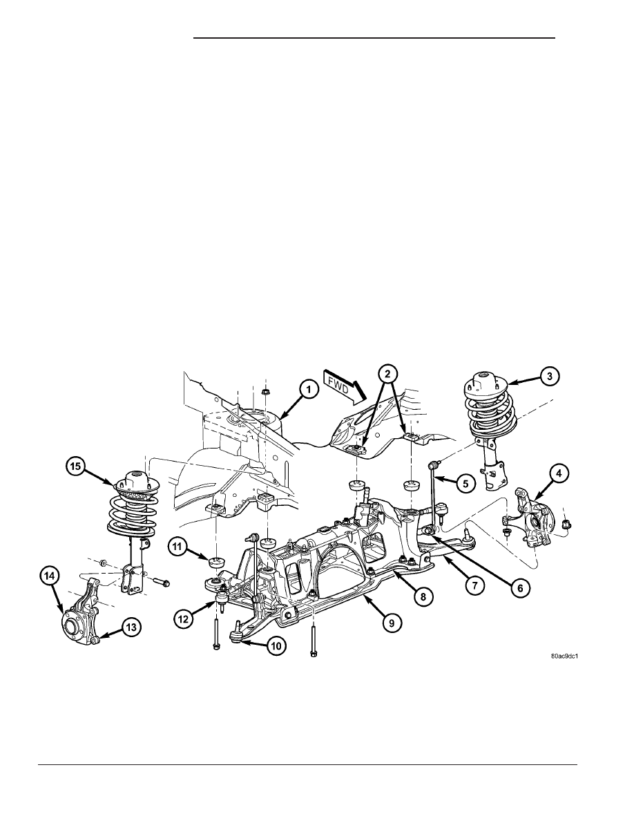
This vehicle has a MacPherson Strut type front

suspension (Fig. 1).

OPERATION - FRONT SUSPENSION

The front suspension allows each wheel on a vehi-

cle to adapt to different road surfaces and conditions
without greatly affecting the opposite wheel and the
ability to control the vehicle. Each side of the front
suspension is allowed to pivot so the vehicle can be
steered in the direction preferred.

A strut assembly is used in place of the front sus-

pension upper control arm and upper ball joint.
When a vehicle strikes a bump, the force is trans-
ferred through the hub, bearing, and knuckle, into
the strut assembly to absorb the force and dampen it.
The top of the strut is mounted directly to the strut
tower of the vehicle. During steering maneuvers, the
strut assembly (through a pivot bearing in the upper

strut mount) and steering knuckle (through the lower
ball joint) turn as an assembly.

STANDARD PROCEDURE - LUBRICATION

There are no serviceable lubrication points on the

front suspension. The ball joints are sealed-for-life
and require no maintenance. The lower ball joints
have special grease fitting caps that prevent normal
grease gun attachment. This has been done to elimi-
nate the possibility of over-filling, damaging the non-
vented seal. Do not attempt to remove the special
grease fitting cap and replace it with a normal grease
zirc fitting.

CAUTION: No attempt should be made to replace
the ball joint grease fitting cap with a normal zirc
fitting or fill the ball joint with grease. Damage to
the grease seal can result.

Fig. 1 Front Suspension

1 - TOWER
2 - CROSSMEMBER TAPPING PLATES
3 - LEFT STRUT ASSEMBLY
4 - LEFT STEERING KNUCKLE (WITH HUB AND BEARING)
5 - STABILIZER BAR LINK
6 - STABILIZER BAR
7 - LEFT LOWER CONTROL ARM
8 - CRADLE/CROSSMEMBER

9 - CRADLE/CROSSMEMBER REINFORCEMENT
10 - BALL JOINT
11 - ISOLATOR BUSHING
12 - STEERING GEAR TIE ROD
13 - RIGHT STEERING KNUCKLE
14 - RIGHT HUB AND BEARING
15 - RIGHT STRUT ASSEMBLY

2 - 2

FRONT SUSPENSION

RS

SPECIFICATIONS

FRONT SUSPENSION FASTENER TORQUE

DESCRIPTION

N·m

Ft.

Lbs.

In.

Lbs.

Ball Joint Nut

108

80

Cradle Crossmember
Mounting Bolts

163

120

Cradle Crossmember
Reinforcement Bolts - Size
M-14

153

113

Cradle Crossmember
Reinforcement Bolt - Size
M-12

106

78

Cradle Crossmember
Reinforcement Bolts - Size
M-10

61

45

Disc Brake Adapter
Mounting Bolts

169

125

Hub And Bearing Mounting
Bolts

65

45

Hub And Bearing Axle Hub
Nut

244

180

Lower Control Arm Pivot
Bolt

183

135

Stabilizer Bar Bushing
Retainer Bolts

68

50

Stabilizer Bar Link Nuts

88

65

Strut Body/Tower Mounting
Nuts

28

21

250

Strut Clevis-to-Knuckle Nuts

81 +

90°

turn

60 +

90°

turn

Strut Shaft Nut

100

75

Tie Rod Adjuster Jam Nut

75

55

Tie Rod Steering Arm Nut

75

55

Wheel Mounting (Lug) Nuts

135

100

SPECIAL TOOLS

FRONT SUSPENSION

Puller C-3894A

Press, Ball Joint C-4212F

Installer, Ball Joint 6758

Wrench, Strut Rod Nut 6864

RS

FRONT SUSPENSION

2 - 3

FRONT SUSPENSION (Continued)

BUSHINGS

REMOVAL - STABILIZER BAR CUSHION

(1) Raise Vehicle. Refer to Hoisting in Lubrication

and Maintenance.

(2) Remove the 2 bolts fastening the emission leak

detection pump to the cradle crossmember reinforce-
ment.

(3) Move the leak detection pump to the side

allowing access to the stabilizer bar cushion retain-
ers.

(4) Remove the nut and bolt securing each stabi-

lizer bar cushion retainer to the cradle crossmember
(Fig. 2) and remove the retainers.

(5) Remove each stabilizer bar cushion from the

stabilizer bar by opening the slit in the cushion and
peeling it off the stabilizer bar.

INSTALLATION - STABILIZER BAR CUSHION

(1) Install each new cushion on stabilizer bar by

spreading cushion at slit and forcing it onto stabilizer
bar.

NOTE: Cushions must be installed on stabilizer bar
so the square corner of the bushing will be down
and slit in cushion will be facing the rear of the
vehicle when the stabilizer bar is installed (Fig. 3).

(2) Place stabilizer bar into mounted position with

cushions properly aligned.

(3) Hook each retainer into cradle crossmember

mounting hole and over cushion.

(4) Install each mounting bolt from rear of cradle

crossmember through retainer. Install the two nuts
and tighten to 68 N·m (50 ft. lbs.) torque.

(5) Reattach emission leak detection pump to cra-

dle crossmember reinforcement with two mounting
bolts.

(6) Lower the vehicle.

REMOVER/INSTALLER, BUSHING 8460

REMOVER/INSTALLER, BALL JOINT 8490

Fig. 2 Front Stabilizer Bar Cushion Retainers

1 - STEERING GEAR
2 - STABILIZER BAR
3 - RAISED BEAD
4 - FRONT CRADLE CROSSMEMBER
5 - RETAINERS

Fig. 3 Correctly Installed Stabilizer Bar Cushion

1 - SLIT IN SWAY BAR BUSHING.
2 - SQUARE CORNER
3 - SWAY BAR
4 - SWAY BAR ISOLATOR BUSHING

2 - 4

FRONT SUSPENSION

RS

FRONT SUSPENSION (Continued)

HUB / BEARING

DESCRIPTION

The front wheel bearing and front wheel hub of

this vehicle are a hub and bearing unit type assem-
bly (Unit III). This unit combines the front wheel
mounting hub (flange) and the front wheel bearing
into a sealed one-piece unit. The hub and bearing is
mounted to the center of the steering knuckle (Fig.
1). It is retained by four mounting bolts accessible
from the inboard side of the steering knuckle. The
hub flange has five wheel mounting studs.

The wheel mounting studs used to mount the tire

and wheel to the vehicle are the only replaceable
components of the hub and bearing assembly. Other-
wise, the hub and bearing is serviced only as a com-
plete assembly.

OPERATION

The hub and bearing has internal bearings that

allow the hub to rotate with the driveshaft, along
with the tire and wheel. The five wheel mounting
studs mount the tire and wheel, and brake rotor to
the vehicle.

DIAGNOSIS AND TESTING - HUB AND
BEARING

The condition of the front hub and bearing assem-

bly is diagnosed using the inspection and testing pro-
cedure detailed below.

The bearing contained in the Unit III front hub/

bearing assembly will produce noise and vibration
when worn or damaged. The noise will generally
change when the bearings are loaded. A road test of
the vehicle is normally required to determine the
location of a worn or damaged bearing.

Find a smooth level road surface and bring the

vehicle up to a constant speed. When vehicle is at a
constant speed, swerve the vehicle back and forth
from the left and to the right. This will load and
unload the bearings and change the noise level.
When bearing damage is slight, the noise is some-
times noticeable at lower speeds and at other times
is more noticeable at speeds above 105 km/h (65
mph).

REMOVAL

NOTE: Replacement of the Unit III front hub/bearing
assembly can be normally done without having to
remove the steering knuckle from the vehicle. In the
event that the hub/bearing is frozen in the steering
knuckle and cannot be removed by hand, it will
have to be pressed out of the steering knuckle. The
steering knuckle will require removal from the vehi-
cle to allow the hub/bearing assembly to be

pressed out of the steering knuckle. (Refer to 2 -
SUSPENSION/FRONT/KNUCKLE - REMOVAL)

(1) Raise vehicle. (Refer to LUBRICATION &

MAINTENANCE/HOISTING - STANDARD PROCE-
DURE)

(2) Remove wheel lug nuts, and front tire and

wheel assembly.

(3) Remove the cotter pin, nut lock and spring

washer from the stub axle (Fig. 4).

(4) With aid of a helper applying the brakes to

keep the front hub from turning, remove the hub nut
(Fig. 4).

(5) Remove disc brake caliper and adapter as an

assembly from knuckle as shown (Fig. 5). Hang
assembly out of the way using a bungee cord or wire.
Do not allow caliper hang by brake hose.

(6) Remove brake rotor from hub and bearing (Fig.

5).

(7) Push in on end of driveshaft stub shaft, push-

ing its splines out of the hub splines.

(8) Remove the four hub and bearing mounting

bolts from the rear of steering knuckle (Fig. 6). Use
care not to come in contact with and damage
the ABS tone wheel on the driveshaft stub shaft
upon bolt removal.

(9) Remove the hub and bearing assembly from

the steering knuckle.

INSTALLATION

CAUTION: Hub and bearing assembly mounting
surfaces on the steering knuckle and stub axle (Fig.
7) must be smooth and completely free of foreign
material or nicks prior to installing hub and bearing
assembly.

Fig. 4 Hub Nut

1 - HUB NUT
2 - NUT LOCK
3 - COTTER PIN
4 - SPRING WASHER

RS

FRONT SUSPENSION

2 - 5


Content   ..  10  11  12  13   ..