Chrysler PT Cruiser. Manual - part 995


  Index      Chrysler     Chrysler PT Cruiser - service repair manual 2005 year


Search            


Content   ..  993  994  995  996   ..


Chrysler PT Cruiser. Manual - part 995


torque converter slip difference (difference be-
tween engine and turbine speed) is within 60 RPM.
Then the LR/TCC solenoid is fully energized
(FEMCC / 100% duty cycle). Torque converter slip
is monitored in FEMCC to ensure adequate clutch
capacity.
Transmission Effects: EMCC will still be avail-
able after code is set. MIL will illuminate after 5
minutes of accumulated slip in FEMCC. The trans-
mission will attempt normal operation (not in
Limp-in) even after the MIL is illuminated.
Possible causes:

> Worn pump bushing and/or failed torque con-

verter - both should be replaced during a rebuild
with code P0740(38) present

> Solenoid/Pressure Switch assembly.

Name of code: P0750(41) - LR Solenoid Circuit
P0755(42) - 2/4 Solenoid Circuit
P0760(43) - OD Solenoid Circuit
P0765(44) - UD Solenoid Circuit
When monitored: Ignition key is turned from off
position to run position and/or ignition key is
turned from crank position to run position, then
every 10 seconds thereafter, or when a gear ratio or
pressure switch error DTC is detected.
Set condition: All four solenoids are tested for
continuity continuously immediately upon start up
and during vehicle operation. For solenoids that
are currently energized, power is momentarily in-
terrupted, then reenergized. For solenoids that are
not currently energized, the solenoid is momen-
tarily energized, then de-energized. Under both
situations, if an inductive spike is not sensed by the
PCM during the continuity check, it is re-tested
twice. If it fails the test the third time, the appro-
priate code is set.

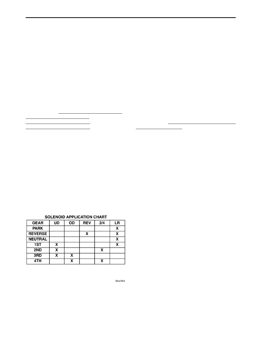
Theory of operation: Four solenoids are used to
control the friction elements (clutches). The conti-
nuity of the solenoids circuits are periodically
tested. Each solenoid is turned on or off depending
on its current state. An inductive spike should be
detected by the PCM during this test. If no spike is
detected, the circuit is tested again to verify the

failure. In addition to the periodic testing, the
solenoid circuits are tested if a gear ratio or pres-
sure switch error occurs. In this case, one failure
will result in the appropriate code being set.
Transmission Effects: The MIL will illuminate
and the transmission goes into neutral if code is set
above 35 Km/h (22 MPH), Limp-in mode when
vehicle speed is below 35 Km/h (22 MPH).
Possible causes:

> Open or shorted solenoid circuit(s) between PCM

and Transmission Solenoid/Pressure Switch as-
sembly

> Open ground circuit

> PCM connector problems.

> Solenoid/Pressure Switch connector problem.

> Solenoid/Pressure Switch assembly.

> PCM

Name of code: P1776(47) - Solenoid Switch Valve
Latched in LR Position
When monitored: Continuously when doing par-
tial or full EMCC (PEMCC or FEMCC)
Set condition: If the transmission senses the LR
pressure switch closing while performing PEMCC
or FEMCC. This code will be set after two unsuc-
cessful attempts to perform PEMCC or FEMCC.
Theory of operation: The solenoid switch valve
(SSV) controls the direction of the transmission
fluid when the LR/TCC solenoid is energized. SSV
will be in the downshifted position in 1st gear, thus
directing the fluid to the LR clutch circuits. In 2nd,
3rd, and 4th, the SSV will be in the upshifted
position and directs the fluid into the torque con-
verter clutch (TCC).

When doing PEMCC or FEMCC, the LR pres-

sure switch should indicate no pressure if the SSV
is in the TCC position. If the LR pressure switch
indicates pressure while in PEMCC or FEMCC,
EMCC operation is aborted and inhibited to avoid
inadvertent application of the LR clutch. Partial
EMCC will be attempted if the LR pressure switch
does not indicate pressure. A second detection of
LR pressure results in setting the code.
Transmission Effects: At speeds above 72 Km/h
(45 MPH), EMCC is inhibited. Once speed falls
below 72 Km/h (45 MPH), the transmission will go
into Limp-in mode and the MIL will illuminate
after 5 minutes of substituted operation.
Possible causes:

> Valve body - Solenoid valve stuck in LR position

> Intermittent short to ground or open circuit in

LR Pressure Switch Sense circuit (with code 24
only)

> Solenoid/Pressure Switch (with code P0841(24)

only)

> PCM (with code P0841(24) only)

12

GENERAL INFORMATION

Name of code: P0736(50) - Gear Ratio Error in
Reverse
P0731(51) - Gear Ratio Error in 1st
P0732(52) - Gear Ratio Error in 2nd
P0733(53) - Gear Ratio Error in 3rd
P0734(54) - Gear Ratio Error in 4th
P0715(56) - Input Speed Sensor Error
P0720(57) - Output Speed Sensor Error
P1794(58) - Speed Sensor Ground Error
When monitored: The transmission gear ratio is
monitored continuously while the transmission is
in gear.
Set condition: This code is set if the gear ratio is
not correct for a period of time.

– Codes 50 through 54 sets if the ratio of the

input RPM (Nt) to the output RPM (No) does
not match the given gear ratio.

– Code 56 sets if there is an excessive change in

input RPM in any gear

– Code 57 sets if there is an excessive change in

output RPM in any gear

– Code 58 sets after a PCM reset in neutral and

Nt/No equals a ratio of input to output of 2.50

A hard code sets within 3 seconds, an intermit-

tent code sets within 15 seconds.
Theory of operation: The transmission system
uses two speed sensors, one to measure input RPM
and one to measure output RPM. These inputs are
essential for proper transmission operation. There-
fore, the integrity of this data is verified through
the following checks:

1. When in gear, if the gear ratio does not compare

to a known gear ratio, the corresponding in-gear
trouble code is set (codes 50 through 54).

2. An excessive change in input or output speeds

indicating signal intermittent will result in
codes 56 and/or 57 being set.

3. After a PCM reset in neutral, observing erratic

output and input speed sensor signals indicates
a loss of the common speed sensors ground. This
sets a code 58.

Transmission Effects: The transmission will not
go into Limp-in mode until three gear ratio error
events occur in a given key start also the MIL will
illuminate after 5 minutes of substituted opera-
tion. This allows for intermittent problems to cor-
rect themselves without opening the relay. How-
ever, if a gear ratio error develops, a code is always
set, but if the condition corrects itself the transmis-
sion will continue without requiring the ignition
key to be cycled on and off. Many different events
could occur given the range of failures possible for
codes 50 through 58. The following are a few
examples:

– Codes 51, 52, 53, 54, 56, and 57 at speeds

above 72 Km/h (45 MPH) - The appropriate

code is set, EMCC is aborted and current gear
is maintained. If while still traveling above
72 Km/h (45 MPH), the gear ratio becomes
valid again, EMCC will reengage and normal
operation will resume. If the gear ratio be-
comes intermittent and recovers three times
in a given key start, the current gear will be
maintained and EMCC inhibited. Then the
transmission will go into Limp-in mode if
throttle is applied below 72 Km/h (45 MPH) or
at 35 Km/h (22 MPH) with closed throttle.

– Codes 51, 52, 53, 54, 56, and 57 at speeds

between 35 and 72 Km/h (22 and 45 MPH) - If
one of these codes is set between 35 and 72
Km/h (22 and 45 MPH), the current gear will
be maintained until the gear ratio problem
corrects itself. If throttle is applied, the trans-
mission will go to 2nd gear. If this happens
and the gear ratio problem goes away, normal
operation will resume. If three gear ratio
problems are identified in a given key start,
the current gear will be frozen until throttle is
applied. The transmission will then go into
Limp-in mode with throttle applied at speeds
between 35 and 72 Km/h (22 and 45 MPH)

– Codes 51, 52, 53, 54, 56, and 57 at speeds

below 35 Km/h (22 MPH) - If a gear ratio
problem is identified below 35 Km/h (22
MPH), the transmission will immediately
substitute second gear for the current gear. If
the gear ratio problem goes away, normal
operation will resume. If three gear ratio
problems are identified in a given key start,
the transmission will go into Limp-in mode.

Possible causes:
Code P0736(50) - Excludes geartrain failures
which should be obvious upon disassembly

> If code P0944(35) is also set, follow diagnostic

procedure for code P0944(35) first

> Valve body - #1 ball check or LR switch valve

sticking - may also set code P0731(51)

> Speed sensor or associated wiring - may also set

codes P0731(51), P0715(56), or P0720(57)

> Failed or slipping LR clutch - may also set code

P0731(51)

– LR seal leakage (Intermittent no drive or

reverse)

– Sticky LR accumulator seals (Intermittent no

drive or reverse)

> Failed reverse clutch (hard code)

– OD/Rev lip seal leakage

– Worn reaction shaft support seal rings

– Snap ring out of position

13

GENERAL INFORMATION

Code P0731(51) - Excludes geartrain failures
which should be obvious upon disassembly

> If code P0944(35) is also set, follow diagnostic

procedure for code P0944(35) first

> Valve body - #1 ball check or LR switch valve

sticking - may also set code P-0736(56) or have
no Reverse

> Speed sensor or associated wiring - may also set

codes P0736(50), P0715(56), or P0720(57)

> Failed or intermittent slipping UD clutch - may

also set P0732(52), or P0733(53)

– UD seal leakage (intermittent)

– Worn input clutch hub bushing (hard code at

heavy throttle)

– Sticky UD accumulator seals (intermittent)

– Worn reaction shaft support seal rings (hard

code at heavy throttle)

– Solenoid pack (UD pressure in 4th gear)

> Failed or slipping LR clutch - may also set code

P0736(56) or have no Reverse

– LR seal leakage (Intermittent)

– Sticky LR accumulator seals (Intermittent)

Code P0732(52) - Excludes geartrain failures
which should be obvious upon disassembly

> If code P0944(35) is also set, follow diagnostic

procedure for code P0944(35) first

> Failed or slipping 2/4 clutch - may also set code

P0734(54)

– 2/4 seat leakage (intermittent)

– Sticky accumulator seals (intermittent)

> Failed or intermittent slipping UD clutch - may

also set code P0731(51) and/or P0733(53)

– UD seal leakage (intermittent)

– Worn input clutch hub bushing (hard code at

heavy throttle)

– Sticky UD accumulator seals (intermittent)

– Worn reaction shaft support seal rings (hard

code at heavy throttle)

– Solenoid pack (UD pressure in 4th gear)

Code P0733(53) - Excludes geartrain failures
which should be obvious upon disassembly

> If code P0944(35) is also set, follow diagnostic

procedure for code P0944(35) first

> Failed or slipping OD clutch - may also set code

P0734(54)

– OD and Reverse inner and outer lip seal

leakage (usually hard code)

– Sticky OD accumulator seals (intermittent)

– Worn reaction shaft support seal rings (hard

code at heavy throttle)

– Broken OD/UD tapered snap ring - (hard code

at heavy throttle)

> Failed or intermittent slipping UD clutch - may

also set code P0731(51) and/or P0732(52)

– UD seal leakage (intermittent)

– Worn input clutch hub bushing (hard code at

heavy throttle)

– Sticky UD accumulator seals (intermittent)

– Worn reaction shaft support seal rings (hard

code at heavy throttle)

– Solenoid pack (UD pressure in 4th gear)

Code P0734(54) - Excludes geartrain failures
which should be obvious upon disassembly

> If code P0944(35) is also set, follow diagnostic

procedure for code P0944(35) first

> Failed or slipping OD clutch - may also set code

P0733(53)

– OD and Reverse inner and outer lip seal

leakage (usually hard code)

– Sticky OD accumulator seals (intermittent)

– Worn reaction shaft support seal rings (hard

code at heavy throttle)

– Broken OD/UD tapered snap ring - (hard code

at heavy throttle)

> Failed or slipping 2/4 clutch - may also set code

P0732(52)

– 2/4 seal leakage (intermittent)

– Sticky accumulator seals (intermittent)

Codes P0715(56) and P0720(57)

> Failed input or output speed sensor (intermit-

tent or hard code)

> Shorted or open wiring between PCM and speed

sensor(s) (intermittent)

> PCM Connector problems and/or Speed Sensor

connector

Code P1794(58)

> Open or shorted speed sensor ground (speed

sensor ground is different from chassis ground)

> Open or shorted Temperature Sensor wiring to

TRS

> TRS - Will also set code P1799(74)

> PCM

Name of code: P0952(69) - AutoStick Sensor Cir-
cuit Low (If equipped)
When monitored: Whenever the engine is run-
ning.
Set condition:
1) The transmission shift lever is not in AutoStick
and either the upshift or downshift switch is
closed.
2) Upshift and downshift switches closed at the
same time.

14

GENERAL INFORMATION

Theory of operation: In the AutoStick Mode
(manual shift mode), upshifts and downshifts are
actuated manually. Shift requests are detected by
monitoring the upshift and downshift switches.
The PCM monitors the above set conditions. A set
condition will be tolerated for up to 15 seconds
before setting a code.
Transmission Effects: The OD position shift
schedule is substituted while operating in the Auto-
Stick gear selector position. No Limp-in mode occurs.
Possible causes:

> Wiring or connector problems

> AutoStick switch failure

> PCM

Name of code: P1797(71) - Manual Shift Overheat
When monitored: Whenever the engine is run-
ning.
Set condition:

1. If the engine temperature exceeds 124°C

(255°F) while operating in AutoStick mode.

2. If the transmission temperature exceeds 135°C

(275°F) while in AutoStick mode

Theory of operation: Transmission and engine
temperatures are monitored during vehicle opera-
tion. If conditions occur causing the engine or
transmission to overheat, the AutoStick mode will
be canceled, and a code will be set.
Transmission Effects: The 3 position shift sched-
ule that is used in non-AutoStick applications is
substituted while operating in the AutoStick gear
selector position. No Limp-in mode occurs.
Possible causes:

> Engine overheat - refer to service manual for

diagnosis and repair

> Transmission Overheat

– Restricted transmission cooling system

– Transmission fluid overfilled

– Radiator fan not functioning properly

– Extended driving in low gear

NOTE: Strenuous driving conditions may
cause the vehicle to overheat. If the driver
operates in or initiates AutoStick with an
overheated vehicle, the code will be set.

Name of code: P0897(73) - Worn Out/Burnt Trans-
axle Fluid
When monitored: At every Fully Electronically
Modulated Converter Clutch (FEMCC) to Partial
Electronically

Modulated

Converter

Clutch

(PEMCC) transition miles when A/C compressor
clutch is being cycled.
Set condition: The code will be set if vehicle
shudder is detected 20 times when the A/C clutch is
cycled.

Theory of operation: While in 3rd or 4th FEMCC
and just before the A/C clutch engages, the Power-
train Control Module (PCM) requests the Trans-
mission Control System to momentarily establish
PEMCC operation. If vehicle shudder is detected
during the FEMCC to PEMCC transition, a
counter is incremented. If the count reaches 20, the
trouble code is set. The driver may then notice
harsh bumps when the A/C clutch is being cycled,
but vehicle shudder will be eliminated. After 35
OBDII (EURO STAGE III OBD) warm-up cycles or
if the code is cleared, PEMCC will be reactivated to
see if shudder is still present. If one shudder event
occurs, the code will be reset. Clearing the code and
running battery disconnect with the DRBIII

t is the

only way to reset the shudder counter from 20 back
to zero.
Transmission Effects: This code does not cause
the transmission to go into Limp-in mode. How-
ever, once the code is set, FEMCC to PEMCC
operation before the A/C clutch engagement will be
disabled for 35 OBDII (EURO STAGE III OBD)
warm up starts.
Possible causes:

> Degraded transmission fluid

> Wheels severely out of alignment

> Internal torque converter problem

Name of code: P0218(75) - High Temperature
Operation Activated.

NOTE: This DTC is an informational DTC
designed to aid the technician in diagnosing
shift quality concerns.

When monitored: Whenever the engine is run-
ning.
Set condition: Immediately once the Overheat
Shift Schedule is activated.
Theory of operation: If the transmission oil
temperature rises above 115°C (240°F), the over-
heat shift schedule is activated refer to Transmis-
sion Operation as a function of Transmission Oil
Temperature and the code is set. The DTC is an
information code only and is being set to aid the
technician in determining root cause of a customer
driveability issue. The code is also intended to alert
the technician to determine if a cooling system
malfunction has occurred or if an additional trans-
mission air to oil cooler should be added to the
vehicle if the customer regularly drives in a man-
ner that overheats the transmission. Extended
operation above 115°C (240°F) will reduce the
durability of the transmission and should be
avoided. Correcting the cooling system malfunction
or installing an additional transmission oil cooler
will improve transmission durability especially for
customers who operate in city/construction stop

15

GENERAL INFORMATION


Content   ..  993  994  995  996   ..