Chrysler PT Cruiser. Manual - part 977


  Index      Chrysler     Chrysler PT Cruiser - service repair manual 2005 year


Search            


Content   ..  975  976  977  978   ..


Chrysler PT Cruiser. Manual - part 977


(2) Rotate the blower motor clockwise until the tab

snaps into the locked position, approximately 1/8
turn.

(3) Connect the blower motor wire harness connec-

tor.

(4) Reconnect the negative battery cable.

DEFROSTER DUCT

REMOVAL

(1) Remove the instrument panel from the vehicle

(Refer to 23 - BODY/INSTRUMENT PANEL/IN-
STRUMENT PANEL ASSEMBLY - REMOVAL).

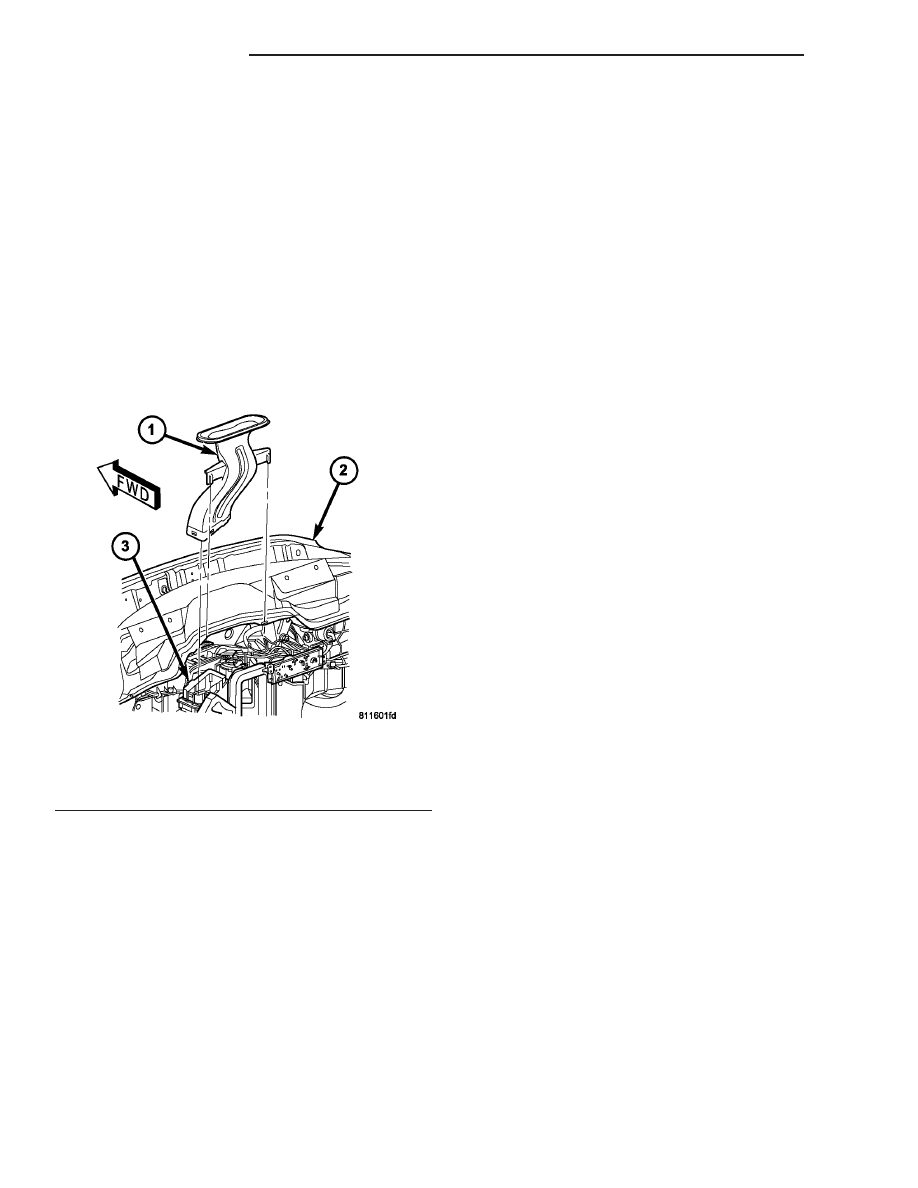
(2) Remove the defroster duct from the top of the

HVAC housing (Fig. 6).

INSTALLATION

(1) Install the defroster duct onto the top of the

HVAC housing. Snap the retainers into place.

(2) Install the instrument panel (Refer to 23 -

BODY/INSTRUMENT

PANEL/INSTRUMENT

PANEL ASSEMBLY - INSTALLATION).

FLOOR DISTRIBUTION DUCTS

REMOVAL

(1) Remove the center floor console (Refer to 23 -

BODY/INTERIOR/CENTER

CONSOLE

-

REMOVAL).

(2) Remove the screws that secure the left and

right floor distribution ducts to the floor (Fig. 7).

(3) Disengage the floor distribution ducts from

each other.

(4) Disengage the floor distribution duct from the

rear seat elbow duct located at the bottom of the
HVAC housing.

(5) Remove both floor distribution ducts from the

vehicle.

(6) If necessary, remove the rear seat elbow duct

from the bottom of the HVAC housing.

INSTALLATION

(1) If removed, install the rear seat elbow duct to

the bottom of the HVAC housing.

(2) Position both floor distribution ducts into the

vehicle.

(3) Engage the floor distribution duct to the rear

seat elbow duct located at the bottom of the HVAC
housing.

(4) Engage the floor distribution ducts to each

other.

(5) Install the screws that secure the left and right

floor distribution ducts to the floor. Tighten the
screws to 2 N·m (17 in. lbs.).

(6) Install the center floor console (Refer to 23 -

BODY/INTERIOR/CENTER CONSOLE - INSTALLA-
TION).

Fig. 6 Defroster Duct - LHD Shown, RHD Typical

1 - DEFROSTER DUCT
2 - COWL
3 - HVAC HOUSING

24 - 30

DISTRIBUTION

PT

BLOWER MOTOR (Continued)

HVAC HOUSING

REMOVAL

WARNING: On vehicles equipped with airbags, dis-
able the airbag system before attempting any steer-
ing wheel, steering column, or instrument panel
component diagnosis or service. Disconnect and
isolate the battery negative (ground) cable, then
wait two minutes for the airbag system capacitor to
discharge before performing further diagnosis or
service. This is the only sure way to disable the air-
bag system. Failure to take the proper precautions
could result in an accidental airbag deployment and
possible personal injury or death.

WARNING: Refer to the applicable warnings and
cautions for this system before performing the fol-
lowing operation (Refer to 24 - HEATING & AIR
CONDITIONING/PLUMBING - WARNINGS) and (Refer
to 24 - HEATING & AIR CONDITIONING/PLUMBING -
CAUTIONS). Failure to follow the warnings and cau-
tions could result in possible personal injury or
death.

NOTE: The HVAC housing must be removed from
the vehicle and the two halves of the housing sep-
arated for service access of the heater core, A/C
evaporator and the mode, recirculation and blend-
air doors.

(1) Recover the refrigerant from the refrigerant

system (Refer to 24 - HEATING & AIR CONDITION-
ING/PLUMBING

-

STANDARD

PROCEDURE

-

REFRIGERANT SYSTEM RECOVERY).

(2) Partially

drain

the

engine

cooling

system

(Refer to 7 - COOLING/ENGINE/COOLANT - STAN-
DARD PROCEDURE - DRAINING COOLING SYS-
TEM).

(3) Disconnect and isolate the negative battery

cable.

(4) Remove the coolant recovery container (Refer

to 7 - COOLING/ENGINE/COOLANT RECOVERY
CONTAINER - REMOVAL).

(5) Remove the screw that secures the accumulator

mounting bracket to the body.

(6) Remove the two bolts securing the accumulator

tubes to the evaporator terminal block and discon-
nect the tubes from the terminal block.

(7) Remove the seals from the refrigerant lines fit-

tings and discard.

(8) Install plugs in, or tape over all of the opened

refrigerant line fittings and evaporator tubes.

Fig. 7 Floor Distribution Ducts - LHD Shown, RHD Typical

1 - HVAC HOUSING
2 - SCREW (4)
3 - RIGHT FLOOR DISTRIBUTION DUCT

4 - LEFT FLOOR DISTRIBUTION DUCT
5 - REAR SEAT ELBOW DUCT

PT

DISTRIBUTION

24 - 31

FLOOR DISTRIBUTION DUCTS (Continued)

(9) Disconnect the vacuum harness at the power

brake booster (Fig. 8).

(10) Remove the rubber drain tube extension from

the condensation drain tube (Fig. 9).

(11) Disconnect the heater hoses from the heater

core tubes. Install plugs in, or tape over the opened
heater core tubes to prevent coolant spillage during
housing removal.

(12) Remove three HVAC housing retaining nuts

located on the dash panel in the engine compart-
ment.

(13) Remove the instrument panel from vehicle

(Refer to 23 - BODY/INSTRUMENT PANEL/IN-
STRUMENT PANEL ASSEMBLY - REMOVAL).

(14) Remove the mode door and temperature con-

trol cables from the mode door and blend-air door
levers and the HVAC housing (Refer to 24 - HEAT-
ING

& AIR

CONDITIONING/CONTROLS/MODE

DOOR CABLE - REMOVAL) and (Refer to 24 -
HEATING

&

AIR

CONDITIONING/CONTROLS/

TEMPERATURE CONTROL CABLES - REMOVAL).

(15) Remove the defroster and floor distribution

ducts from the HVAC housing (Refer to 24 - HEAT-
ING & AIR CONDITIONING/DISTRIBUTION/DE-
FROSTER DUCTS - REMOVAL) and (Refer to 24 -
HEATING & AIR CONDITIONING/DISTRIBUTION/
FLOOR DISTRIBUTION DUCTS - REMOVAL).

(16) Disconnect the wire harness connectors.
(17) Remove the outboard HVAC housing retaining

screw located in the passenger compartment (Fig.
10).

(18) Remove the remaining nut located on the

dash panel stud.

NOTE: Use care to ensure that the interior is cov-
ered in case of loss of residual fluids from the
heater and evaporator cores.

(19) Remove the HVAC housing from the vehicle.

Fig. 8 A/C Vacuum Line - LHD Shown, RHD Typical

1 - BRAKE POWER BOOSTER
2 - A/C VACUUM CHECK VALVE
3 - VACUUM HARNESS

Fig. 9 Dash Panel - LHD Shown, RHD Typical

1 - BLOWER RESISTOR
2 - EVAPORATOR TAPPING PLATE
3 - DRAIN TUBE
4 - DASH PANEL
5 - HEATER HOSES
6 - RETAINING NUTS (3)

Fig. 10 Housing Screws-LHD Shown, RHD Typical

1 - OUTBOARD RETAINING SCREW
2 - HOUSING SCREW BOSSES
3 - DASH PANEL STUD AND NUT

24 - 32

DISTRIBUTION

PT

HVAC HOUSING (Continued)

DISASSEMBLY

(1) Remove the HVAC housing from the vehicle

(Refer to 24 - HEATING & AIR CONDITIONING/
DISTRIBUTION/HVAC HOUSING - REMOVAL).

(2) Place the HVAC housing in the upright position

on a workbench, making allowance for leakage of flu-
ids.

(3) Separate the air distribution foam seals at the

case parting line (Fig. 11).

(4) Remove the evaporator and heater core tube

foam seals from the housing (Fig. 12).

(5) Remove the retaining clips and screws that

hold the upper and lower housing together.

(6) Separate the two halves of the housing.
(7) Remove the heater core and evaporator from

the lower housing as necessary.

ASSEMBLY

(1) Install the heater and evaporator cores into the

case as necessary.

(2) Position the upper and lower HVAC housings

together.

(3) Install the retaining clips and screws that

secure the upper and lower case housings together.
Tighten the screws to 2 N·m 17 in. lbs.).

(4) Install the evaporator and heater core tube

foam seals onto the housing.

(5) Connect the air distribution outlet foam seals

at the case parting line.

(6) Install the HVAC housing (Refer to 24 - HEAT-

ING & AIR CONDITIONING/DISTRIBUTION/HVAC
HOUSING - INSTALLATION).

INSTALLATION

NOTE: High pressures are produced in the refriger-
ant system when the A/C compressor is operating.
Extreme care must be exercised to make sure that
each of the refrigerant system connections is pres-
sure-tight and leak free.

(1) Position the HVAC housing to the dash panel.
(2) Install the nut onto the dash panel stud.

Tighten the nut to 4.5 N·m (40 in. lbs.).

(3) Install the outboard HVAC housing retaining

bolt. Tighten the bolt to 4.5 N·m (40 in. lbs.).

(4) Connect the wire harness connectors.
(5) Install the defroster and floor distribution

ducts onto the HVAC housing (Refer to 24 - HEAT-
ING & AIR CONDITIONING/DISTRIBUTION/DE-
FROSTER DUCTS - INSTALLATION) and (Refer to
24 - HEATING & AIR CONDITIONING/DISTRIBU-
TION/FLOOR DISTRIBUTION DUCTS - INSTAL-
LATION).

Fig. 11 HVAC Air Distribution Foam Seals - LHD

Shown, RHD Typical

1 - AIR DISTRIBUTION
2 - RECIRCULATION DOOR VACUUM ACTUATOR
3 - AIR INLET
4 - BLOWER MOTOR
5 - CONTROL CABLES
6 - VACUUM HARNESS

Fig. 12 Lower HVAC Housing - LHD Shown, RHD

Typical

1 - EVAPORATOR AND CONNECTION
2 - FOAM SEALS
3 - HEATER CORE AND TUBES
4 - HVAC HOUSING LOWER CASE
5 - HOUSING MOUNTING STUDS
6 - HOUSING DRAIN
7 - WIRING
8 - BLOWER MOTOR AND WHEEL

PT

DISTRIBUTION

24 - 33

HVAC HOUSING (Continued)


Content   ..  975  976  977  978   ..