Chrysler PT Cruiser. Manual - part 895


  Index      Chrysler     Chrysler PT Cruiser - service repair manual 2005 year


Search            


Content   ..  893  894  895  896   ..


Chrysler PT Cruiser. Manual - part 895


DECKLID - PT-27

TABLE OF CONTENTS

page

page

DECKLID - PT-27

REMOVAL

. . . . . . . . . . . . . . . . . . . . . . . . . . . . . 38

INSTALLATION

. . . . . . . . . . . . . . . . . . . . . . . . . 38

DECKLID GAS PROP - PT-27

REMOVAL

. . . . . . . . . . . . . . . . . . . . . . . . . . . . . 39

INSTALLATION

. . . . . . . . . . . . . . . . . . . . . . . . . 39

DECKLID HANDLE - PT-27

REMOVAL

. . . . . . . . . . . . . . . . . . . . . . . . . . . . . 39

INSTALLATION

. . . . . . . . . . . . . . . . . . . . . . . . . 39

DECKLID HINGE - PT-27

REMOVAL

. . . . . . . . . . . . . . . . . . . . . . . . . . . . . 40

INSTALLATION

. . . . . . . . . . . . . . . . . . . . . . . . . 40

DECKLID LATCH - PT-27

REMOVAL

. . . . . . . . . . . . . . . . . . . . . . . . . . . . . 40

INSTALLATION

. . . . . . . . . . . . . . . . . . . . . . . . . 40

DECKLID LATCH STRIKER - PT-27

REMOVAL

. . . . . . . . . . . . . . . . . . . . . . . . . . . . . 41

INSTALLATION

. . . . . . . . . . . . . . . . . . . . . . . . . 41

DECKLID LOCK CYLINDER - PT-27

REMOVAL

. . . . . . . . . . . . . . . . . . . . . . . . . . . . . 41

INSTALLATION

. . . . . . . . . . . . . . . . . . . . . . . . . 41

DECKLID TRIM PANEL - PT-27

REMOVAL

. . . . . . . . . . . . . . . . . . . . . . . . . . . . . 42

INSTALLATION

. . . . . . . . . . . . . . . . . . . . . . . . . 42

DECKLID - PT-27

REMOVAL

(1) Release decklid latch and open decklid.
(2) Remove decklid trim panel. (Refer to 23 -

BODY/DECKLID/DECKLID

TRIM

PANEL

-

REMOVAL).

(3) Disconnect decklid wire harness from body wire

harness.

(4) Support decklid on a suitable lifting device.
(5) Disengage clips attaching gas prop rod support-

ing decklid. (Refer to 23 - BODY/DECKLID/GAS
PROP ROD - REMOVAL).

(6) Remove bolts attaching decklid hinge to decklid

(Fig. 1) and (Fig. 2).

(7) With assistance, remove liftgate from vehicle.

INSTALLATION

(1) With assistance, place decklid in position on

vehicle (Fig. 1) and (Fig. 2).

(2) Install bolts attaching decklid hinge to decklid.

Tighten bolts to 33 N·m (24 ft. lbs.) torque.

(3) Install gas prop rods. (Refer to 23 - BODY/

DECKLID/GAS PROP ROD - INSTALLATION).

(4) Remove lifting device from under decklid.
(5) Connect decklid wire harness into body wire

harness.

(6) Install decklid trim panel. (Refer to 23 - BODY/

DECKLID/DECKLID TRIM PANEL - INSTALLA-
TION).

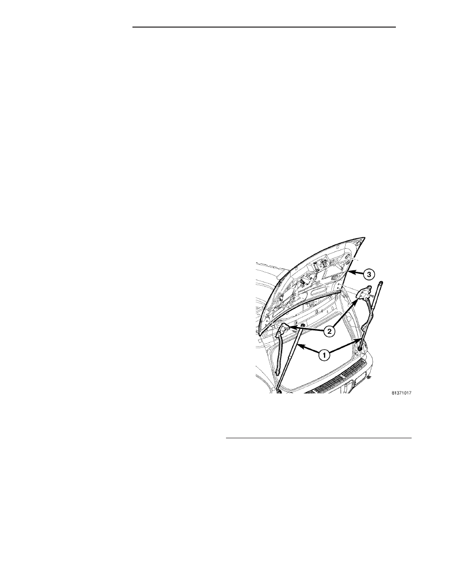
Fig. 1 DECKLID HINGE

1 - GAS PROP ROD
2 - DECKLID HINGE
3 - DECKLID

23 - 38

DECKLID - PT-27

PT

(7) Verify decklid alignment. The decklid should

have a gap to adjacent panels and fit flush across the
gaps. The gap is;

• 7 mm (0.280 in.) to the fascia,

• 6 mm (0.240 in.) to the decklid header,

• 4 mm (0.160 in.) to the body side.

DECKLID GAS PROP - PT-27

REMOVAL

(1) Open decklid.
(2) Remove the gas prop rod lock clips (Fig. 3).
(3)

Remove gas prop-rod from mounting studs.

INSTALLATION

(1) Install gas prop rod to mounting studs (Fig. 3).
(2) Install the gas prop-rod lock clips.
(3) Close decklid.

DECKLID HANDLE - PT-27

REMOVAL

(1) Release decklid latch and open decklid.
(2) Remove decklid trim panel. (Refer to 23 -

BODY/DECKLID/DECKLID

TRIM

PANEL

-

REMOVAL).

(3) Disconnect cylinder link and handle to latch

link by unsnapping the retainer clip and rolling it
clear of link.

(4) Remove the emblem spring nuts (Fig. 4).
(5) Remove the handle attaching nuts.
(6) Remove handle from decklid.

INSTALLATION

(1) Place decklid handle into position (Fig. 4).
(2) Install the handle attaching nuts.
(3) Install the emblem spring nuts.

Fig. 2 DECKLID

1 - DECKLID EMBLEM SPRING NUT(S)
2 - DECKLID OUTSIDE CHROME HANDLE
3 - DECKLID
4 - DECKLID OUTSIDE BEZEL
5 - DECKLID HANDLE ATTACHING NUT(S)

Fig. 3 DECKLID GAS PROP ROD

1 - DECKLID GAS PROP ROD
2 - BALL STUD(S)

Fig. 4 DECKLID

1 - DECKLID EMBLEM SPRING NUT(S)
2 - DECKLID OUTSIDE CHROME HANDLE
3 - DECKLID
4 - DECKLID OUTSIDE BEZEL
5 - DECKLID HANDLE ATTACHING NUT(S)

PT

DECKLID - PT-27

23 - 39

DECKLID - PT-27 (Continued)

(4) Place cylinder link and handle to latch link

into position. Connect the retainer clip by rolling clip
over and snapped into position.

(5) Install decklid trim panel. (Refer to 23 - BODY/

DECKLID/DECKLID TRIM PANEL - INSTALLA-
TION).

(6) Verify decklid operation.

DECKLID HINGE - PT-27

REMOVAL

(1) Release decklid latch and open decklid.
(2) Support decklid on a suitable lifting device.
(3) Disengage clips attaching gas prop rod support-

ing decklid. (Refer to 23 - BODY/DECKLID/GAS
PROP ROD - REMOVAL).

(4) Remove bolts attaching decklid hinge to decklid

and to body side (Fig. 5).

(5) Remove hinge from vehicle.

INSTALLATION

(1) Place hinge into position.
(2) Install bolts attaching decklid hinge to decklid

and to body side (Fig. 5).

(3) Engage clips attaching gas prop rod supporting

decklid. (Refer to 23 - BODY/DECKLID/GAS PROP
ROD - INSTALLATION).

(4) Remove support decklid on a suitable lifting

device.

(5) Release decklid latch and open decklid.

(6) Verify decklid alignment. The decklid should

have a gap to adjacent panels and fit flush across the
gaps. The gap is;

• 7 mm (0.280 in.) to the fascia,

• 6 mm (0.240 in.) to the decklid header,

• 4 mm (0.160 in.) to the body side.

DECKLID LATCH - PT-27

REMOVAL

(1) Release decklid latch and open decklid.
(2) Remove decklid trim panel. (Refer to 23 -

BODY/DECKLID/DECKLID

TRIM

PANEL

-

REMOVAL).

(3) Disconnect decklid latch wire harness from

body wire harness.

(4) Disconnect cylinder link and handle to latch

link by unsnapping the retainer clip and rolling it
clear of link releasing links (Fig. 6).

(5) Remove attaching screws.
(6) Remove decklid latch assembly from vehicle.

INSTALLATION

(1) Place decklid latch assembly into position.
(2) Install attaching screws (Fig. 6).
(3) Place cylinder link and handle to latch link

into position on latch. Connect the retainer clip by
rolling clip over and snapped into position.

Fig. 5 DECKLID HINGE

1 - GAS PROP ROD
2 - DECKLID HINGE
3 - DECKLID

Fig. 6 DECKLID LOCK ASSEMBLY

1 - LOCK CYLINDER LINK
2 - LOCK CYLINDER RETAINER
3 - DECKLID LOCK ASSEMBLY
4 - LOCK CYLINDER GASKET
5 - DECKLID
6 - DECKLID LATCH ASSEMBLY
7 - ATTACHING SCREWS

23 - 40

DECKLID - PT-27

PT

DECKLID HANDLE - PT-27 (Continued)

(4) Connect decklid latch wire harness to body

wire harness.

(5) Install decklid trim panel. (Refer to 23 - BODY/

DECKLID/DECKLID TRIM PANEL - INSTALLA-
TION).

DECKLID LATCH STRIKER -
PT-27

REMOVAL

(1) Open decklid.
(2) Mark outline of striker on sill to aid installa-

tion.

(3) Remove screws attaching striker to sill (Fig. 7).
(4) Remove striker from vehicle.

INSTALLATION

(1) Place striker in position on vehicle (Fig. 7).
(2) Align striker to outline mark on sill.
(3) Install screws attaching striker to sill. Tighten

screws to 28 N·m (21 ft. lbs.) torque.

(4) Verify decklid alignment and operation.

DECKLID LOCK CYLINDER -
PT-27

REMOVAL

(1) Release decklid latch and open decklid.
(2) Remove decklid trim panel. (Refer to 23 -

BODY/DECKLID/DECKLID

TRIM

PANEL

-

REMOVAL).

(3) Disconnect lock assembly wire harness from

decklid wire harness.

(4) Disconnect cylinder link by unsnapping the

retainer clip and rolling it clear of link.

(5) Remove lock cylinder clip from lock assembly

(Fig. 8).

(6) Remove lock cylinder assembly from decklid.

INSTALLATION

(1) Place lock cylinder assembly into position.
(2) Install lock cylinder clip onto lock assembly

(Fig. 8).

(3) Place cylinder link into position on latch. Con-

nect the retainer clip by rolling clip over and snapped
into position.

(4) Connect lock assembly wire harness to decklid

wire harness.

(5) Install decklid trim panel. (Refer to 23 - BODY/

DECKLID/DECKLID TRIM PANEL - INSTALLA-
TION).

(6) Verify decklid alignment and operation.

Fig. 7 DECKLID LATCH STRIKER

1 - DECKLID LATCH STRIKER
2 - ATTACHING SCREW(S)
3 - DECKLID OPENING LOWER PANEL

Fig. 8 DECKLID LOCK ASSEMBLY

1 - LOCK CYLINDER LINK
2 - LOCK CYLINDER RETAINER
3 - DECKLID LOCK ASSEMBLY
4 - LOCK CYLINDER GASKET
5 - DECKLID
6 - DECKLID LATCH ASSEMBLY
7 - ATTACHING SCREWS

PT

DECKLID - PT-27

23 - 41

DECKLID LATCH - PT-27 (Continued)


Content   ..  893  894  895  896   ..